background image

12

SERVICING

Always disconnect the appliance from the
electricity and gas mains before servicing.

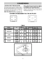
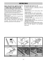
11) REPLACING HOTPLATE PARTS

Remove the pan supports and the burner tops.
Remove the burner fixing screws "V" (fig. 14). Pull
off the control knobs. Lift off the hotplate top.
The burners (fig.15), taps (fig. 16) and electrical
components are all now accessible (fig. 17). 

NB:

the ignition bar must be removed before

replacing the taps in appliances with automatic
ignition systems.
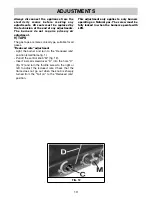
It is advisable to change seal "D" whenever a tap
is replaced to ensure a gas tight seal.
After servicing, check appliance is gas sound.
When checking for gas leaks do not use washing
up liquid - this can corrode. Use a product
specifically manufactured for leak detection.

Greasing the taps (see fig. 18 - 19)

If a tap becomes stiff to operate, it must be
immediately greased in compliance with the
following instructions:
- Remove the tap.
- Clean the cone and its housing using a cloth

soaked in diluent.

- Lightly spread the cone with the relative grease.
- Fit the cone back in place, operate it several

times and then remove it again. Eliminate any
excess grease and check that the gas ducts have
not become clogged.

- Fit all parts back in place, complying with the

demounting order in reverse.

- Check the tightness by using soapy water. 

Do not

light flame to check tap.

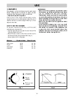
To facilitate the servicing technician’s task, here is a
chart with the types and sections of the powering
cables and the ratings of the electrical
components.

FIG. 17

FIG. 18

FIG. 19

FIG. 14

FIG. 15

FIG. 16

Summary of Contents for 58580

Page 1: ...Cooker hood or appliance name Users Guide Installation Instructions Instruction Number www rangemaster co uk COD 01063GB 30 05 2002...

Page 2: ...ed steel pan support 6 Central enamelled steel pan support for ultra rapid burner 7 Burner n 1 control knob 8 Burner n 2 control knob 9 Burner n 3 control knob 10 Burner n 4 control knob 11 Electric i...

Page 3: ...on small flame fig 1 Always place a lid on the pans Burners Power ratings Pans in cm Ultra rapid 3100 24 26 Rapid 2800 20 22 Semirapid 1750 16 18 Auxiliary 1000 10 14 WARNINGS Never leave the applianc...

Page 4: ...ural air vents clear fig 3 and by activating the mechanical aeration device suction hood or electric fan fig 4 and fig 5 Intensive and lengthy use of the appliance may require additional ventilation T...

Page 5: ...use abrasive powders Do not allow vinegar coffee milk salted water lemon or tomato juice to remain in contact with the enamelled surfaces for long periods of time WARNINGS Before refitting the burner...

Page 6: ...with the installation dimensions see fig 7 8 The appliance is class 3 and should therefore installed built in as detailed in these instructions 4 FIXING THE HOTPLATE The hotplate has a special seal th...

Page 7: ...r vent of effective area 50cm2 is required while if the volume exceeds 11m3 no air vent is required However if the room has a door that opens directly to the outside no air vent is required even when...

Page 8: ...No part of the pipe must be able to touch parts the temperature of which exceeds 75 C The pipe must not be pulled or twisted throttled or tightly bent It must not come into contact with sharp edges or...

Page 9: ...erature rise of 50 C in any part Never use adaptors or inline connectors since these could cause false contacts and dangerous overheating When the appliance is connected straight to the electricity ma...

Page 10: ...ight the burner and turn to the Reduced rate position small flame fig 1 Pull off the control knob M fig 12 Insert a small screwdriver D into the hole C fig 12 and turn the throttle screw to the right...

Page 11: ...diameter of the injectors and the working pressures of the various types of gas CONVERSIONS BURNER ARRANGEMENT ON THE HOTPLATE BUTANE 28 30 225 90 1400 3100 62 PROPANE 37 222 90 1400 3100 62 NATURAL...

Page 12: ...is can corrode Use a product specifically manufactured for leak detection Greasing the taps see fig 18 19 If a tap becomes stiff to operate it must be immediately greased in compliance with the follow...

Page 13: ...YPE OF SINGLE PHASE HOTPLATE CABLE POWER SUPPLY CABLE TYPES AND SECTIONS ATTENTION If the power supply cable is replaced the installer should leave the earth wire longer than the other conductors fig...

Page 14: ...bar Propane 37 mbar Natural 20 mbar Tot Nom Gas Rate 7 3 kW Tot Nom L P G Rate 531 g h Voltage 230 V Frequency 50 Hz 5 BURNERS Category II2H3 Butane 28 30 mbar Propane 37 mbar Natural 20 mbar Tot Nom...

Page 15: ...r adjustments Do not use re conditioned or unauthorized gas controls If repairs or adjustments are required contact our service provider on 0845 603512 specifying the type of fault and the model of th...

Page 16: ...16 V I...

Reviews: