background image

9

8) ELECTRICAL CONNECTION

Electrical connection must be carried out in
compliance with the standards and
regulations in force.

Before proceeding with the connections, check that: 
- The voltage and power rating of the supply is

suitable for the maximum power draw of the
appliance (see data label fixed to the bottom of
the appliance). 

- The socket or system is equipped with an efficient

earth connection in compliance with the
regulations in force. The manufacturer declines all
responsibility for failure to comply with these
regulations. 

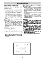
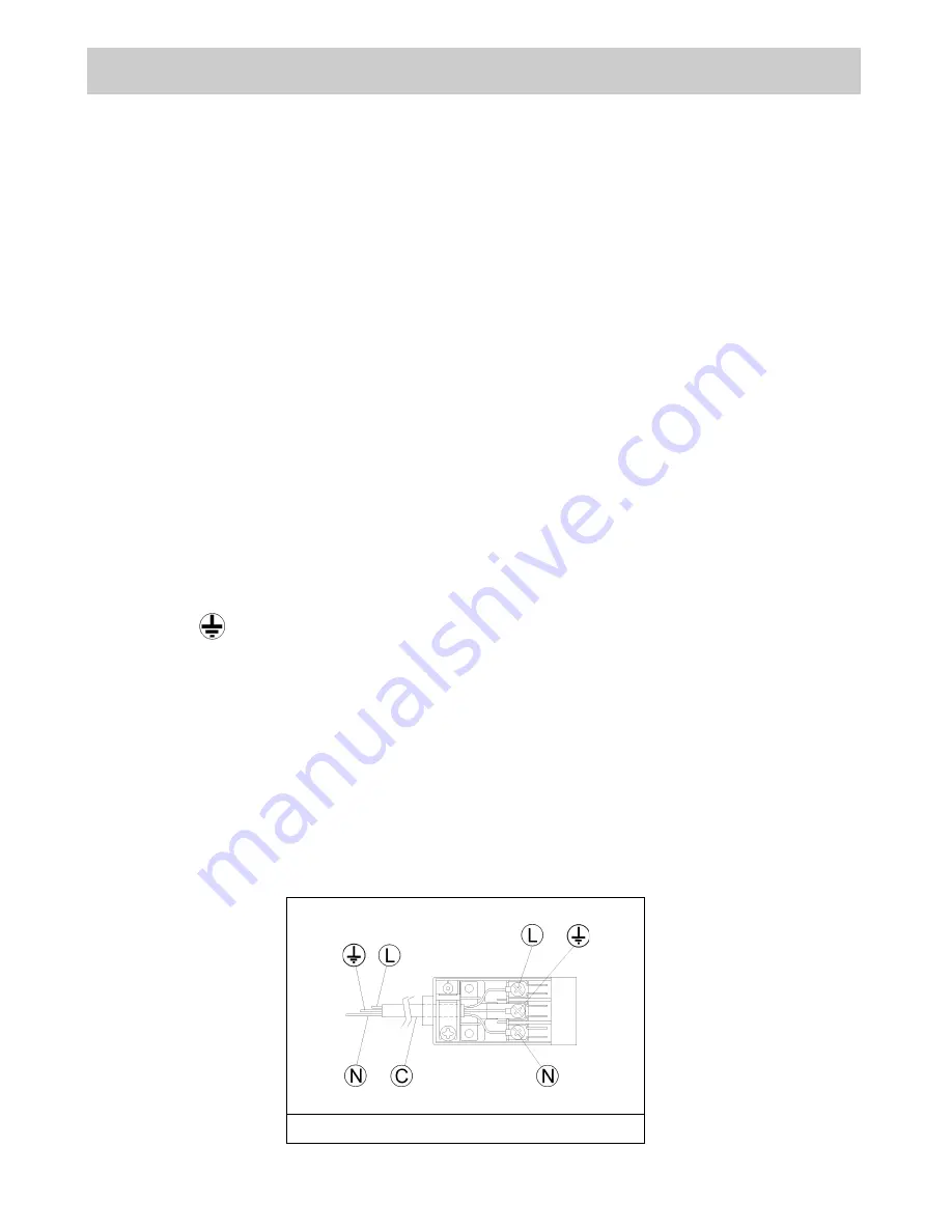
When connection to the electricity main is
made by using a socket: 

- Fit a standard plug to power cable "C" (if without)

(see fig. 11). This plug should be able to bear the
load indicated on the data label. Connect the
wires according to the diagram in fig. 11,
remembering to comply with the following
instructions:

letter L (live) = brown wire;
letter N (neutral) = blue wire;
earth symbol       = yellow-green wire.

- The power cable must be positioned so that it can

never exceed a temperature rise of 50ºC in any
part. 

- Never use adaptors or inline connectors since

these could cause false contacts and dangerous
overheating. 

When the appliance is connected straight to
the electricity main: 

- Install an  all pole cutout between the appliance

itself and the main. This circuit-breaker should be
sized according to the rating of the appliance and
the opening between its’ contacts should be at
least 3 mm. 

- Remember that the earth connection must not be

cut by the switch. 

- The installation may also be protected by an earth

leakage trip. Installers are strongly advised to
connect the yellow- green earthing wire to an
efficient earthing system.

WARNINGS:
The installer should bear in mind that the
mixed appliance is the Y type. The rear wall,
adjacent and surrounding surfaces must
therefore be able to withstand a temperature
rise of 75ºC.
Our appliances are designed and
manufactured in compliance with European
standards    EN 30, EN 60 335-1 and 
EN 60 335-2-6 plus the relative amendments. 
The appliance complies with the provisions of
the following EEC Directives: 
- 89/336 + 92/31 + 93/68 regarding to

electromagnetic compatibility.

- 73/23 + 93/68 regarding electrical safety.

INSTALLATION

FIG. 11

Summary of Contents for 58580

Page 1: ...Cooker hood or appliance name Users Guide Installation Instructions Instruction Number www rangemaster co uk COD 01063GB 30 05 2002...

Page 2: ...ed steel pan support 6 Central enamelled steel pan support for ultra rapid burner 7 Burner n 1 control knob 8 Burner n 2 control knob 9 Burner n 3 control knob 10 Burner n 4 control knob 11 Electric i...

Page 3: ...on small flame fig 1 Always place a lid on the pans Burners Power ratings Pans in cm Ultra rapid 3100 24 26 Rapid 2800 20 22 Semirapid 1750 16 18 Auxiliary 1000 10 14 WARNINGS Never leave the applianc...

Page 4: ...ural air vents clear fig 3 and by activating the mechanical aeration device suction hood or electric fan fig 4 and fig 5 Intensive and lengthy use of the appliance may require additional ventilation T...

Page 5: ...use abrasive powders Do not allow vinegar coffee milk salted water lemon or tomato juice to remain in contact with the enamelled surfaces for long periods of time WARNINGS Before refitting the burner...

Page 6: ...with the installation dimensions see fig 7 8 The appliance is class 3 and should therefore installed built in as detailed in these instructions 4 FIXING THE HOTPLATE The hotplate has a special seal th...

Page 7: ...r vent of effective area 50cm2 is required while if the volume exceeds 11m3 no air vent is required However if the room has a door that opens directly to the outside no air vent is required even when...

Page 8: ...No part of the pipe must be able to touch parts the temperature of which exceeds 75 C The pipe must not be pulled or twisted throttled or tightly bent It must not come into contact with sharp edges or...

Page 9: ...erature rise of 50 C in any part Never use adaptors or inline connectors since these could cause false contacts and dangerous overheating When the appliance is connected straight to the electricity ma...

Page 10: ...ight the burner and turn to the Reduced rate position small flame fig 1 Pull off the control knob M fig 12 Insert a small screwdriver D into the hole C fig 12 and turn the throttle screw to the right...

Page 11: ...diameter of the injectors and the working pressures of the various types of gas CONVERSIONS BURNER ARRANGEMENT ON THE HOTPLATE BUTANE 28 30 225 90 1400 3100 62 PROPANE 37 222 90 1400 3100 62 NATURAL...

Page 12: ...is can corrode Use a product specifically manufactured for leak detection Greasing the taps see fig 18 19 If a tap becomes stiff to operate it must be immediately greased in compliance with the follow...

Page 13: ...YPE OF SINGLE PHASE HOTPLATE CABLE POWER SUPPLY CABLE TYPES AND SECTIONS ATTENTION If the power supply cable is replaced the installer should leave the earth wire longer than the other conductors fig...

Page 14: ...bar Propane 37 mbar Natural 20 mbar Tot Nom Gas Rate 7 3 kW Tot Nom L P G Rate 531 g h Voltage 230 V Frequency 50 Hz 5 BURNERS Category II2H3 Butane 28 30 mbar Propane 37 mbar Natural 20 mbar Tot Nom...

Page 15: ...r adjustments Do not use re conditioned or unauthorized gas controls If repairs or adjustments are required contact our service provider on 0845 603512 specifying the type of fault and the model of th...

Page 16: ...16 V I...

Reviews: