background image

INSTALLATION

Check the appliance is electrically safe when you have finished.

27

Lowering the Two Rear Rollers

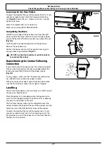
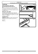
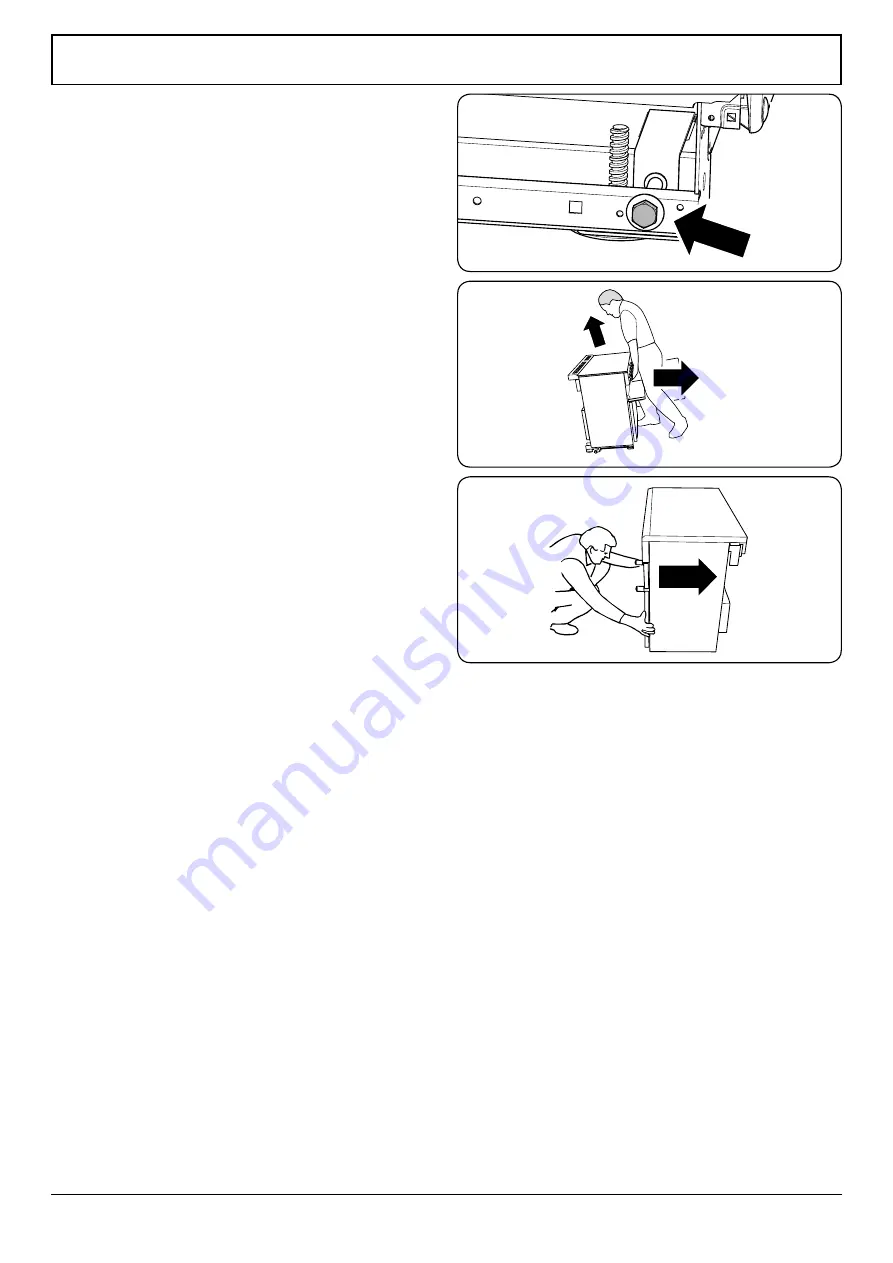
To adjust the height of the rear of the cooker, first fit a 13 mm 

spanner or socket wrench onto the hexagonal adjusting 

nut 

(Fig.8-5)

. Rotate the nut – clockwise to raise – counter-

clockwise to lower.
Make 10 complete (360°) turns clockwise.
Make sure you lower BOTH REAR ROLLERS. 

Completing the Move

Unfold the rear edge of the pack base tray. Open the grill 

door and right-hand oven door so that you can get a good 

grip on the bottom of the fascia panel as you move the oven 

(Fig.8-6)

.

Carefully push the cooker backwards off the pack base. 

Remove the pack base tray.
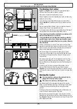
Position the cooker close to its final position, leaving just 

enough space to get behind it 

(Fig.8-7)

.

n

n

DO NOT use the door handles or control knobs to 

manoeuvre the cooker.

Repositioning the Cooker Following 

Connection

If you need to move the cooker once it has been connected 

then you need to unplug it and, having gripped under the 

fascia panel and lifted the front of the cooker slightly  

(Fig.8-6)

.

As you progress, make sure that the electricity cable always 

has sufficient slack to allow the cooker to move.
When you replace the cooker, again check behind to make 

sure that the electricity cable is not caught or trapped.

Levelling

You are recommended to use a spirit level on a shelf in one of 

the ovens to check for level.
Place the cooker in its intended position taking care not to 

twist it within the gap between the kitchen units as damage 

may occur to the cooker or the units.
The front feet and rear rollers can be adjusted to level the 

cooker. To adjust the height of the rear of the cooker, turn the 

adjusting nuts at the front bottom corners of the cooker. 
To adjust the height of the rear of the cooker, use a 13 mm 

spanner or socket wrench to turn the adjusting nuts at the 

front bottom corners of the cooker. To set the front feet turn 

the bases to raise or lower.

ArtNo.010-0004 Moving the cooker

Fig.8-6

Fig.8-5

Fig.8-7

Summary of Contents for Elan 110 Induction G5

Page 1: ...Elan 110 Induction G5 Professional Deluxe 110 Induction G5 USER GUIDE INSTALLATION INSTRUCTIONS...

Page 2: ...Cleaning Your Cooker 19 Hob 19 Glide out Grill 20 Control Panel and Doors 20 Ovens 21 Cleaning Table 22 7 Troubleshooting 23 8 Installation 25 Dear Installer 25 Safety Requirements and Regulations 25...

Page 3: ...atteries are for recyclable hazardous waste When dry batteries are depleted throw into the classification of recyclable waste Throwing waste batteries in the trash can cause serious pollution to the e...

Page 4: ...ntilation below People with respiratory or allergy problems should vacate the area for this brief period Ventilation n n CAUTION The use of a cooking appliance results in the production of heat and mo...

Page 5: ...NOT use aluminium foil to cover shelves linings or the oven roof n n NEVER heat unopened food containers Pressure build up may make the containers burst and cause injury n n DO NOT use unstable saucep...

Page 6: ...ng used for cooking Do not stand or rest heavy objects on the hob Although the ceramic surface is very strong a sharp blow or sharp falling object e g a salt cellar might cause the surface to crack or...

Page 7: ...oker Care As steam can condense to water droplets on the cool outer trim of the oven it may be necessary during cooking to wipe away any moisture with a soft cloth This will also help to prevent soili...

Page 8: ...Note that some stainless steel pans are not suitable for use with an induction hob so please check carefully before purchasing any cookware Pans made of copper aluminium or ceramic are not suitable f...

Page 9: ...Indicator A Automatic Heat up Child Lock L1 L2 Low Temperature Simmer Setting P Power Boost Setting Pan Detector IMPORTANT After use switch off the hob element by its control and DO NOT RELY on the p...

Page 10: ...ning the control knob back to the 0 power setting or turning the control knob to the 9 power setting For your guidance Table 3 2 shows the time available at 100 power depending on the power level sele...

Page 11: ...her as are zones D and E This means that when using zone A on Power Boost and then switching zone B to Power Boost the power to zone A will reduce slightly The last zone switched to Power Boost always...

Page 12: ...ng for the grill to preheat n n DO NOT leave the grill on for more than a few moments without the grill pan underneath it otherwise the knobs may become hot Once the grill has preheated slide the carr...

Page 13: ...and hotter area to the top The exposed top element may cook some foods too quickly so we recommend that the food be positioned in the lower half of the oven to cook The oven temperature may also need...

Page 14: ...ven that circulates hot air continuously which means faster more even cooking The recommended cooking temperatures for a fan oven are generally lower than a conventional oven Note Please remember that...

Page 15: ...eper sounds Turn the Timer knob to the vertical to return to manual cooking To Start and Then Stop the Oven Using the Timer Before you set the clock decide on both the cook time which is the period of...

Page 16: ...Adjusting knob clockwise until the key symbol and OF shows on the display Fig 3 24 Let go of the knobs The programmable oven is now locked as is confirmed by the display showing the time of day alongs...

Page 17: ...ends clear the shelf stops and then lower the front so that the shelf is level and push it fully back Fig 3 31 The Handyrack The Handyrack Fig 3 32 fits to the left hand oven door only Food cooking on...

Page 18: ...for cleaning etc To Remove the Storage Drawer To open simply push the drawer and release The drawer will open Push the ends of the plastic clips down on the left hand side up on the right hand side t...

Page 19: ...Very perishable foods such as pork or fish should be avoided if a long delay period is planned especially in hot weather n n DO NOT place warm food in the oven to be timed n n DO NOT use a timed oven...

Page 20: ...20 40 minutes according to size 2 3 hours 45 60 minutes 40 45 minutes 2 to 3 hours 20 30 minutes 15 20 minutes 15 20 minutes per 500g Steaks according to thickness Conventional Oven Temperature C Shel...

Page 21: ...Spills For spills and boil overs that occur while cooking turn the unit off and wipe the area surrounding the hot zone with a clean paper towel If a spill other than a sugary substance is on the hot z...

Page 22: ...support the side rail with one hand and with the other hand lift the frame up and out of the side clips Fig 6 4 For safety push the side rails back into the grill chamber If you need to remove the si...

Page 23: ...ch have been coated with a special enamel that partly cleans itself This does not stop all marks on the lining but helps to reduce the amount of manual cleaning needed The Cook Clean panels work bette...

Page 24: ...all purpose cloth supermarket Sides and plinth Painted surface Hot soapy water soft cloth Splashback rear grille Enamel or stainless steel Hot soapy water soft cloth Cream cleaner with care if necessa...

Page 25: ...most noticeable when cooking on high power settings or if 5 pans are used simultaneously The type of pan may also contribute to induction noise The cooling fans The cooker incorporates cooling fans T...

Page 26: ...he cooker is not level arrange for your supplier to level it for you The Oven light is not working The bulb has probably burnt out You can buy a replacement bulb which is not covered under the guarant...

Page 27: ...n of Ventilation This appliance is not connected to a combustion products evacuation device Therefore particular attention must be given to the relevant requirements regarding ventilation All rooms re...

Page 28: ...by normal use of the cooker to any material that de laminates or discolours at temperatures less than 65 C above room temperature We recommend a gap of 1110mm between units to allow for moving the coo...

Page 29: ...move the cooker once it has been connected then you need to unplug it and having gripped under the fascia panel and lifted the front of the cooker slightly Fig 8 6 As you progress make sure that the...

Page 30: ...as stated on the voltage label on the cooker through a suitable cooker control unit incorporating a double pole switch having a contact separation of at least 3mm in all poles n n THE COOKER MUST NOT...

Page 31: ...using the 4mm screws Fitting the 1 piece Plinth Loosen the 3 screws along the front bottom edge of the cooker Hook the central keyhole over the central screw Twist and fit each end keyhole over their...

Page 32: ...5 Centre element Code Colour w br White or brown ArtNo 083 0011 IN G5 2 phase Circuit diagram 5 3 4 Earth N 6 N 4 L 2 L 3 E 5 4 3 2 1 Interface board 1 2 5 3 4 Induction unit Hob display w br w br w...

Page 33: ...ion oven control switch Code Description C Clock D1 Right hand fan oven control switch D2 Right hand fan oven thermostat D3 Right hand fan oven element D4 Right hand oven fan F1 Cooling fan F2 Oven li...

Page 34: ...nimum 905mm maximum 930mm Overall width 1100mm Overall depth 597mm to front of fascia 679mm over handles Minimum height above cooker 650mm Refer to Positioning the Cooker Ratings Max 1 85 kW Boost 3 0...

Page 35: ...33...

Page 36: ...400 888 6288 0760 22264283 vatti vatti com cn DocNo 000 0001 Back cover Rangemaster...

Reviews: