background image

3

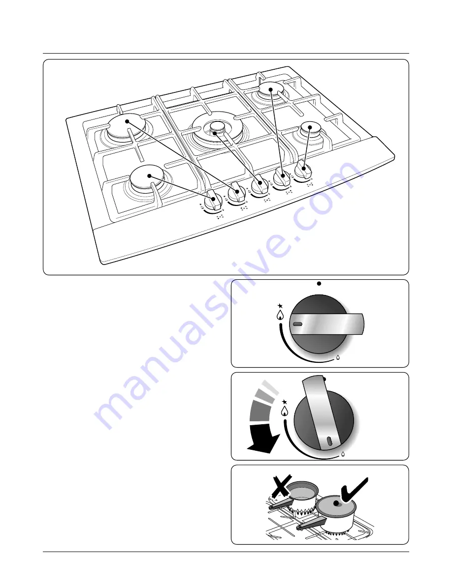
The diagram by each of the control knobs indicates which 

burner that knob operates 

(Fig.2-1)

. Each burner has a 

special Flame Safety Device (FSD) that stops the flow of gas if 

the flame goes out.
To light a burner, push in and turn the associated control 

knob counter-clockwise 

(Fig.2-2)

 to the ‘high’ position 

indicated by the large flame symbol [

]. Keep the knob 

pressed down for 3-5 seconds to let the gas through to the 

burner. The igniter should spark and light the gas.
If, when you let go of the control knob the burner goes out, 

then the safety device has not held in. Turn the control to the 

off position and wait one minute then try again, this time 

holding in the control knob for slightly longer.
Adjust the flame to suit by turning the control knob clockwise 

(Fig.2-3)

.

Ensure that the flames are under the pans. Using a lid will 

help the contents boil more quickly 

(Fig.2-4)

.

Large pans should be spaced well apart.

2.  Hob Overview

ArtNo.316-0006 RG70 hob

ArtNo.316-0001 RG60 hob control

ArtNo.316-0005 RG70 control to low

Fig.2-2

Fig.2-1

Fig.2-3

ArtNo.311-0001 Right pans gas

Fig.2-4

DocNo.021-0002 - Overview RG70 gas

Summary of Contents for RG70

Page 1: ...RG70 Gas Hob User Guide Installation Service Instructions U109926 04...

Page 2: ...ents 1 Before You Start 1 2 Hob Overview 3 3 Cleaning Your Hob 5 4 Troubleshooting 7 5 Installation 8 6 Conversion to LPG Gas 12 7 Circuit Diagram 13 8 Technical Data 14 9 Warranty After Sales Service...

Page 3: ...tor fan Personal Safety Accessible parts will become hot during use and will retain heat even after you have stopped cooking Keep babies and children away from the hob and never wear loose fitting or...

Page 4: ...change in temperature Cleaning In the interests of hygiene and safety the hob should be kept clean at all times as a build up of fats and other foodstuffs could result in a fire Clean only the parts...

Page 5: ...t the gas If when you let go of the control knob the burner goes out then the safety device has not held in Turn the control to the off position and wait one minute then try again this time holding in...

Page 6: ...igned to provide even heat over a large area Fig 2 8 It is ideal for large pans and stir frying For heating smaller pans the smaller hotplate burners may be more efficient Hob Care The burner parts ca...

Page 7: ...city supply before re using the cooker Regular cleaning is recommended For easier cleaning wipe away any spillages immediately Hotplate Burners The burner heads and caps can be removed for cleaning Ma...

Page 8: ...Hot soapy water and a soft cloth remove stubborn stains gently with a nylon scourer Cif cream cleaner and a nylon scourer dishwasher Cif cream cleaner and a nylon scourer dishwasher Cif cream cleaner...

Page 9: ...y Is the power on If not there maybe something wrong with the power supply Are the sparker ignition electrode or burner slots blocked by debris Are the burner trim and caps correctly located See the s...

Page 10: ...ot connected to a combustion products evacuation device Particular attention shall be given to the relevant requirements regarding ventilation In the UK The room containing the hob should have an air...

Page 11: ...ions are shown in Fig 5 1 and the minimum clearances in Fig 5 2 It is recommended that the hob be installed in a worktop with a minimum thickness of 40mm Note If installing the hob over a standard cab...

Page 12: ...art of the pipe must be able to touch parts the temperature of which exceeds 75 C The pipe must not be pulled or twisted throttled or tightly bent It must not come into contact with sharp edges or cor...

Page 13: ...ed from your supplier The colour of the correct fuse carrier is that of the coloured insert in the base of the fuse recess or stated elsewhere on the plug Always state this colour when ordering a repl...

Page 14: ...gas before starting and check that the appliance is gas sound after completion n n Do not use reconditioned or unauthorised gas controls n n Disconnect from the electricity supply before commencing se...

Page 15: ...13 7 Circuit Diagram ArtNo 080 0016 RG70 RGG77 circuit diagram N L A B B B B B A B Spark generator Ignition switch...

Page 16: ...Dimensions Overall height 100 mm 120 mm including gas connector Above worktop 50 mm Below worktop 50 mm Overall width 720 mm see Positioning of Cooker Overall depth 510 mm Space for fixing See Positi...

Page 17: ...purchase invoice and the product code serial number The 2 years free maintenance for the operation of the appliance started from the date of purchase of this product Any cosmetic damage to the applian...

Page 18: ...30...

Page 19: ...31...

Page 20: ...w rangemaster co uk DocNo 000 0001 Back cover Rangemaster Clarence Street Royal Leamington Spa Warwickshire CV31 2AD England Tel 44 0 1926 457400 Fax 44 0 1926 450526 E mail consumers rangemaster co u...

Reviews: