background image

INSTALLATION

Check the appliance is electrically safe when you have finished.

27

Electrical Connection

The cooker must be installed by a qualified electrician, in 
accordance with all relevant British Standards/Codes of 
Practice (in particular BS 7671), or with the relevant national 
and local regulations.

Current Operated Earth Leakage Breakers

The combined use of your induction cooker and other 

domestic appliances may cause nuisance tripping, so we 

recommend that the cooker is protected on an individual 

RCD (Residual Current Device) or RCBO (Residual Current 

Breaker with Overload).

IF IN DOUBT, PLEASE CONSULT A SUITABLY QUALIFIED 

ELECTRICIAN.

 

WARNING: THE APPLIANCE MUST BE EARTHED.

Note:

 The cooker must be connected to the correct electrical 

supply as stated on the voltage label on the cooker, through 
a suitable cooker control unit incorporating a double pole 
switch, having a contact separation of at least 3mm in all 
poles.

 

The cooker MUST NOT be connected to an ordinary 
domestic power point.

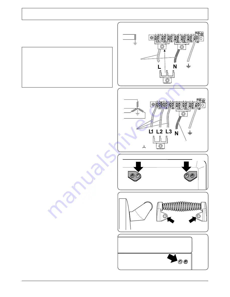
Access to the mains terminal is gained by removing the 
electrical terminal cover box on the back panel. Connect 
the mains cable to the correct terminals for your electrical 
supply type (

Fig.7-11

 and 

Fig.7-12

). Check that the links are 

correctly fitted and that the terminal screws are tight. Secure 
the mains cable using the cable clamp.

Hob Check

Check each cooking zone in turn. Be sure to use pans of the 
correct size and material.

Grill Check

Turn on the grill control and check that the grill heats up.

Oven Check

Set the clock as described earlier, and then turn on the ovens. 
Check the oven fans start to turn and that the ovens heat up.

Fitting the Handles and Handrail 

(depending on model)

Remove the 4mm Allen screws from the doors 

(Fig.7-13)

. Fit 

the door handles and secure using the 4mm screws.

 

The handles should be above the fixings.

Fit the plastic blanking plugs to the fixing holes 

(Fig.7-14)

.

Remove the 4mm Allen screws from the top corners of the 
fascia 

(Fig.7-15)

. Fit the front handrail in position and secure 

using the 4mm screws.

ArtNo.130-0010 Electrical connections single-phase


������������

���������

ArtNo.130-0010 Electrical connections 3-phase

��

��
��

�����
�������������

��������

���������

Fig.7-11

Fig.7-12

ArtNo.215-0026 - Handle gaskets fixed

ArtNo.215-0027 - Elan handle blanking plugs

Art No 215-0028 - Handrail fascia fixings

Fig.7-13

Fig.7-14

Fig.7-15

Summary of Contents for Toledo 110 Ceramic

Page 1: ...Elite 110 Ceramic U110038 02 User Guide Installation Service Instructions...

Page 2: ...3 Location of Cooker 23 Positioning the Cooker 24 Unpacking the Cooker 24 Moving the Cooker 24 Completing the Move 25 Repositioning the Cooker following Connection 25 Levelling 26 Electrical Connectio...

Page 3: ...tchen is well ventilated keep natural ventilation holes open or install a powered cooker hood that vents outside If you have several hotplates on or use the cooker for a long time open a window or tur...

Page 4: ...a aming pan Turn o the controls and then smother a aming pan on a surface unit by covering the pan completely with a well tting lid or baking tray If available use a multipurpose dry chemical or foam...

Page 5: ...ours Fig 1 5 Cleaning DO NOT use abrasive cleaners pads oven aerosols pads or stain removers on the surface In the interests of hygiene and safety the cooker should be kept clean at all times as a bui...

Page 6: ...ity of food a ects the setting required Higher settings are required for larger quantities of food Pots and pans should have thick smooth at bottoms Fig 2 2 This ensures the maximum heat transfer from...

Page 7: ...reheat a covered serving dish for 10 minutes before adding food to it Dual Element Hob Plates The areas marked with two concentric circles have an inner and an outer element Rotate the control knob cl...

Page 8: ...a few moments without the grill pan underneath it otherwise the knobs may become hot Once the grill has preheated take the grill pan out again and put the trivet back in place with the food on it Slid...

Page 9: ...oor should be kept closed while grilling is in progress so saving energy You will also nd that the food needs to be watched and turned less than for normal grilling Preheat this function before cookin...

Page 10: ...Ovens Conventional and Fan ovens Turn the oven knob to the desired temperature Fig 2 14 The oven indicator light will glow until the oven has reached the temperature selected It will then cycle on an...

Page 11: ...ng to keep an eye on the time of day or leave it in the minute minder position as the time ticks down To stop the beeper when it sounds turn the Adjusting knob anti clockwise The cook period which is...

Page 12: ...ny active programs Turn and hold the Timer knob to the clock symbol for about 8 seconds On appears on the display Fig 2 24 While still holding the Timer knob turned to the clock symbol turn the Adjust...

Page 13: ...u must have two numbers clearly in mind the cook period and the stop time Note You cannot set a start time directly this is set automatically by setting the cook period and the stop time Press and hol...

Page 14: ...it will not come on The right hand oven can be operated as usual To activate the key lock Make sure that the clock is in manual mode and cancel any active programs Hold the Minute Minder and Cook per...

Page 15: ...dyrack Fig 2 49 ts to the left hand oven door only Food cooking on it is easy to attend to because it is accessible when the door is open The maximum weight that can be held by the Handyrack is 5 5kg...

Page 16: ...ard Lift up the ends of the plastic clips one each side to release the catches holding the drawer to the side runners and at the same time pull the drawer forward and away from the side runners Fig 2...

Page 17: ...front edge of the oven s wire shelves Other containers should be placed centrally Keep all trays and containers away from the back of the oven as overbrowning of the food may occur For even browning...

Page 18: ...vidual 10 20 minutes 15 20 minutes 15 20 minutes per 500g Steaks according to thickness 45 50 minutes per 500g of mixture 2 2 hours Up to 3 hours 80 90 minutes 15 25 minutes 10 15 minutes 20 30 minute...

Page 19: ...g surface As a nal step wipe the cooking surface with a clean dry paper towel Cleaning Spills For spills and boil overs that occur while cooking turn o the unit and wipe the area surrounding the hot z...

Page 20: ...h side support the side rail with one hand and with the other hand lift the frame up and out of the side clips Fig 5 4 For safety push the side rails back into the grill chamber If you need to remove...

Page 21: ...de Cook Clean panels which have been coated with a special enamel that partly cleans itself This does not stop all marks on the lining but helps to reduce the amount of manual cleaning needed These pa...

Page 22: ...a liquid detergent Stainless steel E Cloth or Vileda Microfibre Plus All Purpose Cloth Freudenberg Household Products LP supermarket Sides and plinth Painted surface Hot soapy water soft cloth Splashb...

Page 23: ...er Therefore it is in your own interest to keep track of this installer so that you can contact them as required Power failure In the event of a failure in the electrical supply remember to reset the...

Page 24: ...care to protect your ngers with a glove in case the bulb should shatter Screw in the new bulb clockwise and then screw the bulb cover back on Turn on the electricity supply and check that the bulb now...

Page 25: ...The cooker may be installed in a kitchen kitchen diner but NOT in a room containing a bath or shower This appliance is designed for domestic cooking only Use for any other purpose could invalidate an...

Page 26: ...Certain types of vinyl or laminate kitchen furniture are particularly prone to heat damage and discolouration We cannot accept responsibility for damage caused by normal use of the cooker to any mate...

Page 27: ...anel as you move the cooker Grip under the fascia panel and lift the front of the cooker slightly Fig 7 9 Carefully push the cooker backwards o the pack base Remove the pack base tray Position the coo...

Page 28: ...t of the rear of the cooker use the levelling tool supplied to turn the adjusting nuts at the front bottom corners of the cooker To set the front feet turn the bases to raise or lower Leave the levell...

Page 29: ...g the electrical terminal cover box on the back panel Connect the mains cable to the correct terminals for your electrical supply type Fig 7 11 and Fig 7 12 Check that the links are correctly tted and...

Page 30: ...screws 1 each end to the inner plinth The height of the outer plinth can be adjusted by sliding it up or down via the slotted hole Fig 7 18 Fitting the Splashback optional The splashback secures to th...

Page 31: ...Left hand front hob energy regulator C Left hand rear hob energy regulator D Right hand rear hob energy regulator E Earth terminal F Right hand front hob dual energy regulator G Right hand warmer hob...

Page 32: ...y br br br br br Code Description A Left hand end dual circuit hob energy regulator B Left hand front hob energy regulator C Left hand rear hob energy regulator D Right hand rear hob energy regulator...

Page 33: ...y br br br br w r bk Code Description A Left hand end dual circuit hob energy regulator B Left hand front hob energy regulator C Left hand rear hob energy regulator D Right hand rear hob energy regul...

Page 34: ...B2 Left hand oven thermostat front switch B3 Left hand oven browning element inner pair B4 Left hand oven top element outer pair B5 Left hand oven base element D Clock E Earth Code Description F1 Rig...

Page 35: ...ment B4 Left hand multi function oven top element outer pair B5 Left hand multi function oven browning element inner pair B6 Left hand multi function oven fan element B7 Left hand multi function oven...

Page 36: ...rol B2a Left hand multi function oven thermostat front switch B3 Left hand multi function oven base element B4 Left hand multi function oven top element outer pair B5 Left hand multi function oven bro...

Page 37: ...convection 2 2kW 2 5kW 3 7kW 2 5kW Energy e ciency class on a scale of A more e cient to G less e cient A B B A Energy consumption based on standard load 0 99kWh 0 90kWh 0 90kWh 0 85kWh Usable volume...

Page 38: ...36...

Page 39: ...37...

Page 40: ...www rangemaster co uk ArtNo 000 0003 CE logo DocNo 000 0001 Back cover Rangemaster...

Reviews: