background image

27

INSTALLATION


Check the appliance is electrically safe when you have finished.

L1

N

L3
L2

3N ac

230/400 V 50 Hz

6 mm² max

10 mm² max

6 mm² max

Fig. 8.11


Fig. 8.12


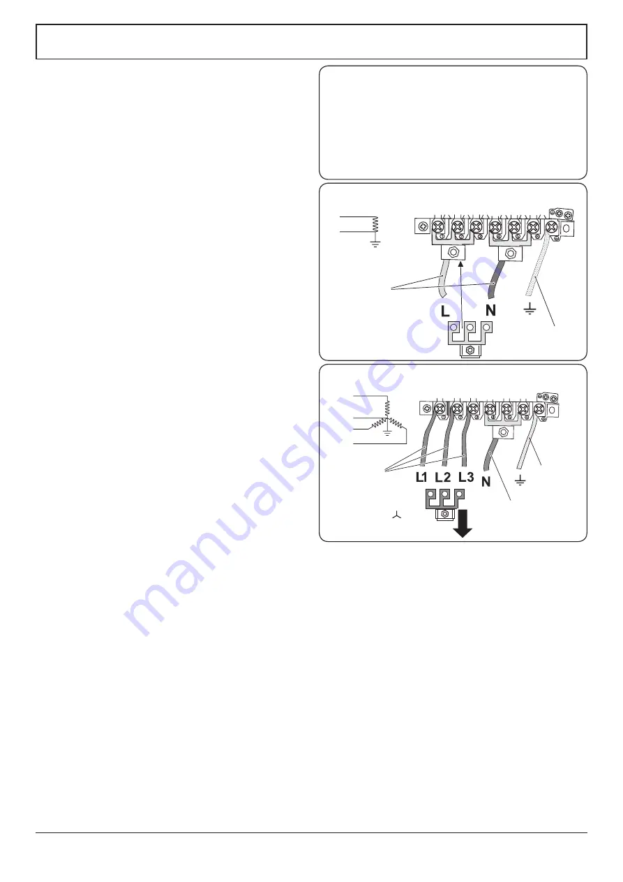
ArtNo.130-0010 Electrical connections single-phase

L

N

230 V ac 50 Hz

10 mm² max

6 mm² max

Current Operated Earth Leakage Breakers

The combined use of your induction cooker and other 

domestic appliances may cause nuisance tripping, so we 

recommend that the cooker is protected on an individual 

RCD (Residual Current Device) or RCBO (Residual Current 

Breaker with Overload).

IF IN DOUBT, PLEASE CONSULT A SUITABLY QUALIFIED 

ELECTRICIAN.

Electrical Connection

The cooker must be installed by a qualified electrician, in 

accordance with all relevant British Standards/Codes of 

Practice (in particular BS 7671), or with the relevant national 

and local regulations.
The cable size and type should be suitable for the 

Electrical Load of the appliance and comply with the local 

requirements as defined in the latest editions of BS 7671 and 

or BS EN 50565-1 Reference B4.

n

n

WARNING: THE APPLIANCE MUST BE EARTHED.

NOTE

: The cooker must be connected to the correct electrical 

supply as stated on the voltage label on the cooker, through 

a suitable cooker control unit incorporating a double-pole 

switch, having a contact separation of at least 3 mm in all 

poles.

n

n

The cooker MUST NOT be connected to an ordinary 

domestic power point.

Access to the mains terminal is gained by removing the 

electrical terminal cover box on the back panel. Connect 

the mains cable to the correct terminals for your electrical 

supply type (

Fig. 8.11

 and 

Fig. 8.12

). Check that the links are 

correctly fitted and that the terminal screws are tight. 
Secure the mains cable using the cable clamp.

Summary of Contents for U110730-02a

Page 1: ...Infusion 110 Induction USER GUIDE INSTALLATION INSTRUCTIONS Built from experience U110730 02a...

Page 2: ...ook Twitter message or Instagram comment 4 We cannot guarantee your kitchen will be professionally photographed 4 Any photographs received and professional photographs taken will belong to AGA Rangema...

Page 3: ...s 11 Accessories 12 3 3 button clock 13 4 Cooking Tips 15 5 Cooking table 16 6 Cleaning your cooker 17 7 Troubleshooting 21 8 Installation 24 Dear Installer 24 Safety requirements and regulations 24 P...

Page 4: ...ii...

Page 5: ...ll become hot during use and will retain heat even after you have stopped cooking Keep babies and children away from the cooker and never wear loose fitting or hanging clothes when using the appliance...

Page 6: ...ate covers of any description These may affect the safe use of your hotplate burners and are potentially hazardous to health NEVER heat unopened food containers Pressure build up may make the containe...

Page 7: ...pans will expose a portion of the surface unit to direct contact and may result in the ignition of clothing Only certain types of glass glass ceramic earthenware or other glazed containers are suitabl...

Page 8: ...hould be washed after use in order to prevent it from becoming scratched or dirty However you should clean the hob with caution as some cleaners can produce noxious fumes if applied to a hot surface D...

Page 9: ...may be necessary during cooking to wipe away any moisture with a soft cloth This will also help to prevent soiling and discolouration of the oven exterior by cooking vapours Fig 1 7 Cleaning Isolate t...

Page 10: ...table for use on an induction hob The kind of pan you use and the quantity of food affects the setting required Higher settings are required for larger quantities of food Pots and pans should have thi...

Page 11: ...of the following induction hob functions Pan Detector H Residual Heat Indicator A Automatic Heat up Child Lock L1 L2 Low Temperature Setting P Power Boost Setting Pan Detector n n IMPORTANT After use...

Page 12: ...er for a specified time before the power is reduced to the level selected When the Automatic Heat up function is activated the hob control display will flash alternately between the A setting and the...

Page 13: ...the power is automatically reduced to setting 9 When using the Power Boost function the cooking zones are linked Fig 2 8 shows the hob layout Zones A and B are linked together as are zones C D and E T...

Page 14: ...es The grill trivet can be removed and the food placed on it while you are waiting for the grill to preheat n n DO NOT leave the grill on for more than a few moments without the grill pan underneath i...

Page 15: ...those for a non fan oven NOTE Please remember that all cookers vary so temperatures in your new ovens may differ to those in your previous cooker Operating the Ovens Conventional and Fan Ovens Turn t...

Page 16: ...n shelf To fit the glide out shelf hook the front of the shelf onto the runners as shown Fig 2 21 The rear of the shelf should rest on the runners in front of the rear stop Fig 2 21 The glide out shel...

Page 17: ...of which an alarm will sound 1 Press the mode M button once Fig 3 2 The bell symbol will flash on the display Select the desired countdown from 00 01h to 23 59h using the button Fig 3 3 The countdown...

Page 18: ...rent time will be displayed along with the word AUTO Fig 3 9 3 Set the oven to the required cooking temperature 4 During the cook period the cook symbol is illuminated in the display 5 When cooking is...

Page 19: ...ble foods such as pork or fish should be avoided if a long delay period is planned especially in hot weather Whole poultry must be thoroughly defrosted before being placed in the oven Check that meat...

Page 20: ...es 10 20 minutes according to size 20 40 minutes according to size 2 3 hours 45 60 minutes 40 45 minutes 2 to 3 hours 20 30 minutes 15 20 minutes 15 20 minutes per 500g Steaks according to thickness C...

Page 21: ...rounding the hot zone with a clean paper towel If a spill other than a sugary substance is on the hot zone do not clean until the unit has completely cooled down and then follow the instructions below...

Page 22: ...you need to remove the side rails to allow cleaning of the grill chamber you can unhook them from the grill chamber sides Fig 6 5 and wipe the sides clean with a soft cloth and mild detergent n n DO...

Page 23: ...ove the cooker forward to gain access to the sides see the Moving the Cooker section under Installation Cook Clean Panels The ovens have side Cook Clean panels which have been coated with a special en...

Page 24: ...ermarket Sides and plinth Painted surface Hot soapy water soft cloth Splashback rear grille Enamel or stainless steel Hot soapy water soft cloth Cream cleaner with care if necessary Control panel Pain...

Page 25: ...le when cooking on high power settings or if 5 pans are used simultaneously The type of pan may also contribute to induction noise The cooling fan The induction hob incorporates a cooling fan This coo...

Page 26: ...er oven door can be adjusted to alter the angle of the door Fig 7 3 Loosen the bottom hinge fixing screws and use the notch and a flat bladed screwdriver to move the position of the hinge to set the h...

Page 27: ...g wrong with the power supply Is the cooker supply on at the isolator switch Has the time of day been set The timed oven is not coming on when automatic cooking Has the oven knob been left in the OFF...

Page 28: ...gned for domestic cooking only Use for any other purpose could invalidate any warranty or liability claim Provision of ventilation This appliance is not connected to a combustion products evacuation d...

Page 29: ...r of the appliance should be heat splash and steam resistant Certain types of vinyl or laminate kitchen furniture are particularly prone to heat damage and discolouration We cannot accept responsibili...

Page 30: ...oor handles or control knobs to manoeuvre the cooker Fitting the Stability Bracket We recommend using a stability bracket first attach the bracket location device to the rear of the cooker Fig 8 8 The...

Page 31: ...671 or with the relevant national and local regulations The cable size and type should be suitable for the Electrical Load of the appliance and comply with the local requirements as defined in the lat...

Page 32: ...er in the instructions and then turn on the ovens Check that the oven fans start to turn and that the ovens start to heat up NOTE The oven light bulb is not included in the guarantee Turn off the oven...

Page 33: ...are for 230V 50Hz Code Description 1 Left hand front element 2 Left hand rear element 3 Right hand rear element 4 Right hand front element 5 Centre element Code Colour w br White brown 1 2 5 3 4 E 5 4...

Page 34: ...at Code Description D3 Right hand oven fan D4 Right hand oven element F Oven light switch G1 Left hand oven light G2 Right hand oven light H Thermal cut out J Neon K Cooling fan Code Colour b Blue br...

Page 35: ...Cooker Ratings Max 1 85 kW Boost 2 5 kW Max 1 85 kW Boost 3 0 kW Max 1 85 kW Boost 2 5 kW Max 1 15 kW Boost 2 0 kW Max 1 15 kW Boost 2 0 kW Zone 1 Zone 2 Zone 3 Zone 5 Zone 4 Hotplate energy saving t...

Page 36: ...nergy Consumption ECElectric cooking Wh kg 172 Zone 3 cm 18 5 Heating Technology Energy Consumption ECElectric cooking Wh kg 180 Zone 4 cm 15 5 Heating Technology Energy Consumption ECElectric cooking...

Page 37: ...ht hand Efficiency Fuel type Electric Cavity type Fanned Power conventional Power forced air convection 2 5 Volume Litres 73 Energy consumption electricity conventional kWh cycle Energy consumption el...

Page 38: ...34 Notes...

Page 39: ...organisations other than those authorised to act on behalf of AGA Rangemaster Exceptions Items not included under the free 1 year guarantee include pan supports griddles wok rings baking trays grill p...

Page 40: ...CV31 2AD England Consumer Services 44 0 800 804 6261 or 0 370 789 5107 from a mobile Fax 44 0 1926 450526 E mail consumers agarangemaster co uk www rangemaster co uk For UK Trade Enquiries Tel 44 0 11...

Reviews: