background image

23


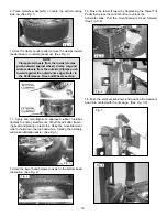
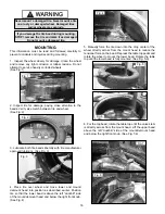
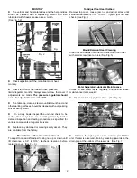
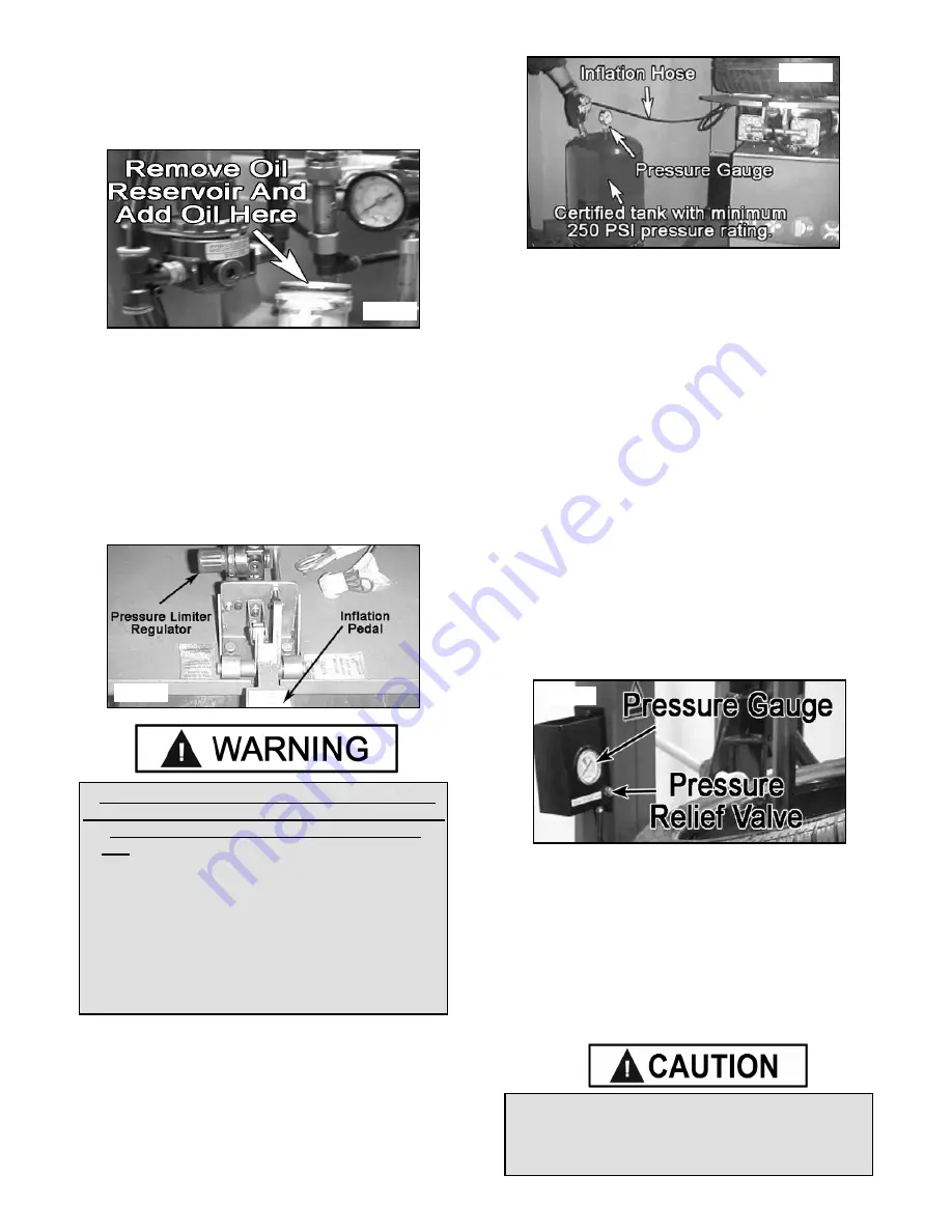
Add oil to the lubricator if the fluid level is below the    

middle of the sight glass. Remove the reservoir by turning 
counter-clockwise and pulling down. Add SAE 10W non-
detergent oil or an air tool oil if necessary.  (See Fig. 1)


Reconnect the air when service/adjustments are 

complete.

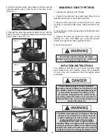
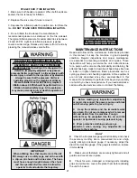
Inflation Pedal Pressure Limiter Maintenance

The inflation pedal pressure limiter helps prevent inflation 
of standard size or larger tires or tubes beyond 60 PSI to           
minimize risk of explosion. This device is for the safety of 
the operator and bystanders. Proper operation of the 
pressure limiter is essential to safe operation of the 
machine. (See Fig. 2)

Check operation of the pressure limiter as follows at least 
once a month:

1. Remove tires and/or wheels from the machine.

2. Connect the inflation hose to an empty service tank with a 
pressure gauge (gauge should read 0). Use a certified tank 
with at least 250 PSI pressure rating.  (See Fig. 3)

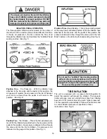
3. Depress inflation pedal to position one to start air flow 
through the hose and into the tank. Maintain a steady 


pressure for constant flow.

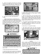
4. Watch the rising pressure on the tank gauge and the 
gauge on the machine. Machine gauge should cycle 
between check and inflation pressures while tank gauge 
climbs steadily. As tank pressure reaches 60 PSI, the 


pressure limiter should stop the air flow automatically. Both 
gauges should read 60 PSI ± 5 PSI.

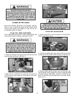
5. If the pressure exceeds 60 PSI, adjust the knob on 
the regulator by lifting the locking cover and turning 


COUNTERCLOCKWISE. After adjustment is made, secure 
cover in the locked position.  

6. Repeat steps 1-6. Re-adjust if necessary.

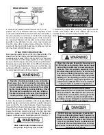
7. After pressure limit has been set, check the manual 
release valve function by pressing the button and releasing 
pressure from the tank until it reaches 50 PSI. Disconnect 
inflation hose, and release air inside tank.   (See Fig. 4)

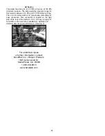
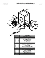
INSTALLATION INSTRUCTIONS

Location

Select a location using the drawings below. The area 
should provide the operator with enough space to use the       
equipment in a safe manner. The area selected should be 
well lit, easy to clean and should be away from oil, grease, 
brake lathe chips, etc. Avoid areas where bystanders and          
customers may be present.

THE PRESSURE LIMITER IS PRE-SET AT THE  

FACTORY AND SHOULD NEED NO ADJUSTMENT. 

ADJUST ONLY IF PRESSURE EXCEEDS 60 

PSI. Operating a tire changer with a defective,       

improperly adjusted, or by-passed pressure limiter 

could result in a tire explosion with severe injury 

or death to the operator or bystanders. Always be 

sure that the pressure limiter is operating properly 

on the machine at all times. Pressure limiter is 

set at 60 PSI. Any required inflation above 60 PSI 

should be performed in an inflation chamber/safety 

cage. A tire explosion may cause personal injury 

or death to operator or bystanders.

Fig. 1

Fig. 2

Fig. 3

Fig. 4

Proper unit installation is necessary for safe use

and efficient operation. Proper installation also 

helps protect the unit from damage and makes 

service easier. Always keep this manual unit.

Summary of Contents for R23

Page 1: ...y proper training and thoughtful operation on the part of the operator DO NOT operate or repair this equipment without reading this manual and the important safety instructions shown inside Keep this...

Page 2: ...prepaid which prove upon inspection to be defective The manufacturer will pay labor costs for the first 12 months only on parts returned as previously described The warranty does not extend to defects...

Page 3: ...lps make tire changing safer However equipment does not take the place of safe operating practices Always wear durable work clothing during tire service activity Shop aprons or shop coats may also be...

Page 4: ...l installation instructions Make sure installation conforms to all applicable Local State and Federal Codes Rules and Regulations such as State and Federal OSHA Regulations and Electrical Codes Carefu...

Page 5: ...This is for ground only 11 DANGER The motor on this machine contains high voltage Disconnect power at the receptacle before performing any electrical repairs Secure plug so that it cannot be accidenta...

Page 6: ...fore demounting or mounting and seating the beads NEVER mount a tire on a damaged or rusty wheel as tire or wheel failure may result during inflation Explosion from failure may result in severe injury...

Page 7: ...or rubber lubricant 11 Combination Mount Demount Head Mounts and demounts tire from wheel 12 Slide Adjustment Handle Adjusts horizontal and vertical slide assembly for proper horizontal and vertical p...

Page 8: ...nit without appropriately rated equipment Be sure the unit is securely attached to any lifting device used Never use the wood shipping skid for mounting the unit Select a location using the drawings o...

Page 9: ...ric shock Never connect the green power cord wire to a live terminal This is for ground only DANGER The motor on this machine contains high voltage Disconnect power at the receptacle before performing...

Page 10: ...not on the tire sidewall 5 Pull the bead breaker shoe away from the machine and roll the wheel into position The valve stem should be in the 2 o clock position 6 Position the bead breaker shoe against...

Page 11: ...nd Wide Side flanges 3 The tire must ALWAYS be demounted or mounted with the wheel positioned on the turntable with the Narrow Side facing upward and the deepest part of the Drop Center facing upward...

Page 12: ...ier See Fig 3 12 Use the lower bead helpers to assist in the bottom bead lubrication See Fig 4 13 Move the tower forward by depressing the Tower Tilt Pedal then press the control button to unlock the...

Page 13: ...e Fig 5 6 19 Insert the smooth curved end of tool bar over the right end knob of the mount demount head and below the top bead of the tire See Fig 7 8 20 Push the tool bar down toward the wheel to lif...

Page 14: ...l bar down toward the wheel to lift the tire bead up and over the right side knob portion of the demount head Hold the tool bar in this position See Fig 5 6 24 Depress the table top pedal to rotate th...

Page 15: ...d bead lifting tool as described earlier paying careful attention not to pinch the tube Depress the table top pedal and rotate only a short distance at a time This allows you to stop the process shoul...

Page 16: ...f the mount demount head and below the right front knob See Fig 4 5 Manually force the tire down into the drop center of the wheel directly across from the mount head to reduce the tensional force on...

Page 17: ...four steps Restraint Bead Seal Bead Seat and Inflation Read the explanation of each step and understand them thoroughly before proceeding Do not force the tire onto the rim Bead damage could result m...

Page 18: ...ated position With the inflation hose attached to the tire valve and the pedal in this position line pressure is allowed to flow through the valve and to the Jet Blast nozzles on the table top for bea...

Page 19: ...edal to position two and hold about one second to begin air flow through tire valve then depress pedal to position three and hold briefly less than 1 full second The blast of air from the jets will ex...

Page 20: ...Fig 1 KEEP HANDS AND FINGERS CLEAR Keep entire body away from the tire 2 Release air pressure from the tire by pressing the manual release valve button NOTE The inflation hose must be attached to the...

Page 21: ...ality stick type pressure gauge If necessary adjust the dial of the machine gauge If the gauge is defective replace it immediately Make sure all fasteners are securely tightened and all guards and cov...

Page 22: ...at regular intervals Replace any damaged or missing safety decal s They are available from the factory Mount Demount Tool Head Adjustment To adjust tool head lift adjust locking nut up or down until...

Page 23: ...exceeds 60 PSI adjust the knob on the regulator by lifting the locking cover and turning COUNTERCLOCKWISE After adjustment is made secure cover in the locked position 6 Repeat steps 1 6 Re adjust if n...

Page 24: ...h a 1 4 pipe thread male fitting for easy connection This connection is located on the right side of the rear of the machine A 1 4 ID hose or pipe for connection to the machine is satisfactory Suffici...

Page 25: ...25...

Page 26: ...26 R23 00 00 REVISION A 22 Tire changer...

Page 27: ...10 x 1 5 x 50 44 2 HHB M8 x 1 5 x 45 45 2 HHB M16 x 13 x 25 46 2 Washer M16 x 35 Flat Item Qty Description 47 1 Lower Tilt Tower Cylinder Pin 48 1 Plastic Plug 49 2 Nut M14 50 2 Screw M14 x 42 51 1 Vo...

Page 28: ...HHB M8 x 1 25 x 68 12 1 Nut M8 x 1 5 13 2 HHB M6 x 1 x 30 14 2 Nut M6 x 1 15 2 Spring 15mm OD x 6mm ID x 42mm 16 1 SHCS M6 x 1 x 16 17 1 Washer M6 Flat 18 3 SHCS M6 x 1 x 10 19 1 Washer M6 Flat 20 1...

Page 29: ...t R23 2 1 R Ring 20mm ID 3 1 Y Ring 20 x 30 x 9 4 4 Nut M8 x 1 25 NL 5 1 Front Cover R23 Jaw Clamp Cylinder 6 1 Banjo Bolt Double 7 2 O Ring 97 x 3mm 8 1 Jaw Clamp Bronse Bearing 9 1 Jaw Clamp Cylinde...

Page 30: ...VISION A 05 Item Qty Description 1 1 Turntable 2 4 Jaw Clamp 3 4 Jaw Clamp Support 4 4 10MM 1 8 Straight Fitting 5 2 Jaw Clamp Slide Block 6 4 HHB M12 x 1 75 x 83 7 12 Washer M12 Flat 8 8 Washer M12 S...

Page 31: ...1 19 40 21 22 23 25 26 27 29 28 30 32 31 37 33 35 34 42 43 36 45 46 48 44 47 38 39 49 37 3 51 1 14 12 5 2 41 4 8 6 7 13 16 15 17 18 20 24 50 11 52 6000307 PEDAL ASSEMBLY 9 10 10 T D 04 00 REVISION A 1...

Page 32: ...M6 14 4 BHPS M3 x 10 15 2 Cam Bracket 16 2 FHS M6 x 1 0 x 16 17 2 Plastic Cam 18 8 Washer M6 Flat 19 2 Cam Plate 20 4 SHCS M6 x 1 0 x 25 21 1 Switch Cover 22 1 Turntable Direction Switch 23 1 Switch...

Page 33: ...6 5 0 187 0 T J 00 07 00 A 05 Item Qty Description 1 1 Motor 110 220 1 5hp 50 60hz 2 4 Washer M8 Flat 3 1 Motor Support Bracket 4 4 Washer M10 Flat 5 4 HHB M8 x 1 25 x 40 6 4 Nut M8 x 1 25 7 8 Rubber...

Page 34: ...4 D 2 X 2 8 T JK 0A 00 A 02 Item Qty Description 1 1 Rotary Joint Block Bottom 2 2 12mm x 3 8 Straight Fitting 3 2 8mm x 1 4 Straight Fitting 4 1 Rotary Joint Block Top 5 2 10mm x 3 8 90 Fitting 6 2 8...

Page 35: ...3 1 Upper Gearbox Housing 4 1 Gearbox Spindle 5 1 Gearbox Spindle Upper Key 6 1 Gearbox Spindle Lower Key 7 1 Gearbox Spindle 8 1 Gearbox Spindle Upper Key 9 2 Pin 8mm x 20mm 10 1 Gearbox Spindle Low...

Page 36: ...Mounting Bracket 4 2 R Ring 14mm OD 5 1 Foot Pedal Return Spring 6 1 Valve Body 7 1 Fixing Plate 8 5 Air Valv Spacer 9 3 Double Threaded Bolt M6 x 1 0 x 124 10 6 O Ring 9 5 x 4 11 1 Spring Pin 4mm x...

Page 37: ...EXHAUST VALVE ASSEMBLY T K 02 00 00A A 04 Item Qty Description 1 1 Deflating Valve Body 2 2 12mm x 3 8 90 Fitting 3 2 12mm x 3 8 90 Fitting 4 1 8mm x 1 4 90 Fitting 5 1 Deflating Valve Mounting Brack...

Page 38: ...5 7 A 03 Item Qty Description 1 1 Inflator Box Housing 2 1 8mm x 1 8 Straight Fitting 3 1 Air Distributing Valve 4 3 Washer M4 Flat 5 3 Nut M4 x 0 7 6 3 Washer M4 SL 7 1 8mm x 1 4 Straight Fitting 8...

Page 39: ...Valve 2 1 1 4 Female Tee Fitting 3 1 Air Tank 4 2 Double Threaded Union 1 4 5 1 One Way Check Valve 6 1 Quick Connect Nut 7 1 10mm x 2mm O Ring 8 1 Quick Connect 9 1 Connector Lock 10 1 Hose Spring G...

Page 40: ...1 5 2 187 0 16 57 2 5 T LS 02 00A REVISION A 05 Item Qty Description 1 1 BB Cylinder Shaft 445MM 2 1 R Ring 32mm OD 3 12 SHCS M6 x 1 0 x 25 4 12 Washer M6 Flat 5 1 NA 6 1 30 X 20 X 5 O Ring 7 1 8mm x...

Page 41: ...em Qty Description 1 1 Tilt Tower Cylinder Shaft 2 4 Nut M8 NL 3 1 R Ring 30mm OD 4 1 Tilt Tower Cylinder Seal 5 1 Tilt Tower Cylinder Upper Cover 6 1 Tilt Tower Cylinder Bearing 7 2 75 x 2 65 O Ring...

Page 42: ...2 635 1 7 5 A 03 Item Qty Description 1 1 NA 2 1 Air Regulator 3 2 1 4 Tee Fitting 4 1 13mm Female Union 5 2 29 x 2 65 O Ring 6 1 Oil Regulator 7 1 Oil Regulator Cup 8 1 Pressure Gauge 9 1 Air Dryer C...

Page 43: ...5 5 29 5 1 21752 9 9 5004119 HANDLE CONTROLING VALVE Item Qty Description 1 2 Locking Valve Button 2 1 Locking Valve Rod 3 4 8 x 2 65 O Ring 4 3 Locking Valve Spacer 5 1 Locking Valve Front Seal 6 2 6...

Page 44: ...44 3 7 3 5 66 0 PL330B 00 00 REVISION A 04...

Page 45: ...x 1 25 x 25 37 4 Washer M8 SL 38 4 Washer M8 Flat 39 1 Left Tower Upper Support Bracket 40 2 SHCS M12 x 1 75 x 60 Item Qty Description 41 9 Washer M12 Flat 42 11 Washer M12 SL 43 2 Nut M12 NL 44 1 Ass...

Page 46: ..._______________________________________________________________________ _________________________________________________________________________________________ ______________________________________...

Page 47: ...47 This page left intentionally blank...

Page 48: ...48 For Parts Or Service Contact BendPak Inc Ranger Products 1645 Lemonwood Dr Santa Paula CA 93060 Tel 1 805 933 9970 Toll Free 1 800 253 2363 Fax 1 805 933 9160 www bendpak com www rangerproducts com...

Reviews: