


KEEP HANDS AND FINGERS CLEAR.
KEEP ENTIRE BODY AWAY FROM THE TIRE
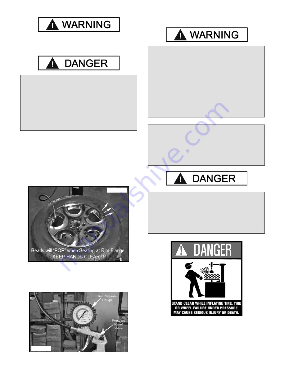
1. Once tire pressure is indicated on the air gauge, continue
to inject air into the tire in short intervals. Check the pressure
frequently. Stand back during bead seat. Keep hands, arms,
and entire body away from tire during this procedure. Tire
beads should move outward and “pop” into their bead seat
position as pressure inside the tire increases. If this does not
happen, a problem exists. Investigate carefully.
(See Fig. 16.4)
2. Release air pressure from the tire by pressing the Manual
Release Valve Button. NOTE: The Inflation Hose must be
attached to the valve stem during this procedure.
(See Fig. 16.5)
STAGE THREE / TIRE INFLATION
27
WARNING!
Check tire pressure frequently. Never exceed
40 PSI while seating beads. Once seated, never
exceed tire manufacturer’s recommended air
pressure. Tires can explode, especially if they are
inflated beyond their limits. At all pressure levels
when inflating through the valve stem, keep hands,
arms, and entire body away from inflating tire.
An exploding tire, wheel, or bead sealing
equipment may propel upward and outward with
sufficient force to cause serious injury or death to
operator or bystander.
MIS-MATCHED TIRES AND WHEELS
Never attempt to mount and inflate mis-matched
tires and wheels. Mis-matched tire and wheel
combinations can explode, causing personal injury
or death to operator and bystanders. For safety, do
not attempt to mount and inflate mis-matched tires
and wheels.
DANGER!
NEVER increase tire pressure to exceed 40 PSI
when attempting Bead Seat. If operator is unable
to obtain Bead Seat, something is wrong. Deflate
tire completely, inspect tire and wheel, correct any
problems found, re-lubricate both tire beads, and
reattempt Bead Seal and Seat procedures. Follow
and follow all safety instructions in this manual
and on machine.
Fig. 16.5
Fig. 16.4
IMPORTANT!
When inflating tires that require more than 60 PSI,
always use a safety cage and air hose with a
clip-on air chuck and in-line valve. The hose must
have enough length between the chuck and the
operation/in-line valve to allow the operator to
stand outside the trajectory.
Summary of Contents for R715
Page 32: ...32...
Page 33: ...33 RECORD ALL MAINTENANCE NOTES AND SERVICE HISTORY HERE...
Page 34: ...34 5 7 5 1 5...


