


10
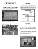
CAUTION!
Handling of the machine must be performed only
with an appropriate lifting device such as a forklift or
shop crane. Only personnel who are experienced and
qualified on material handling procedures should
handle any transportation or moving of machine
.
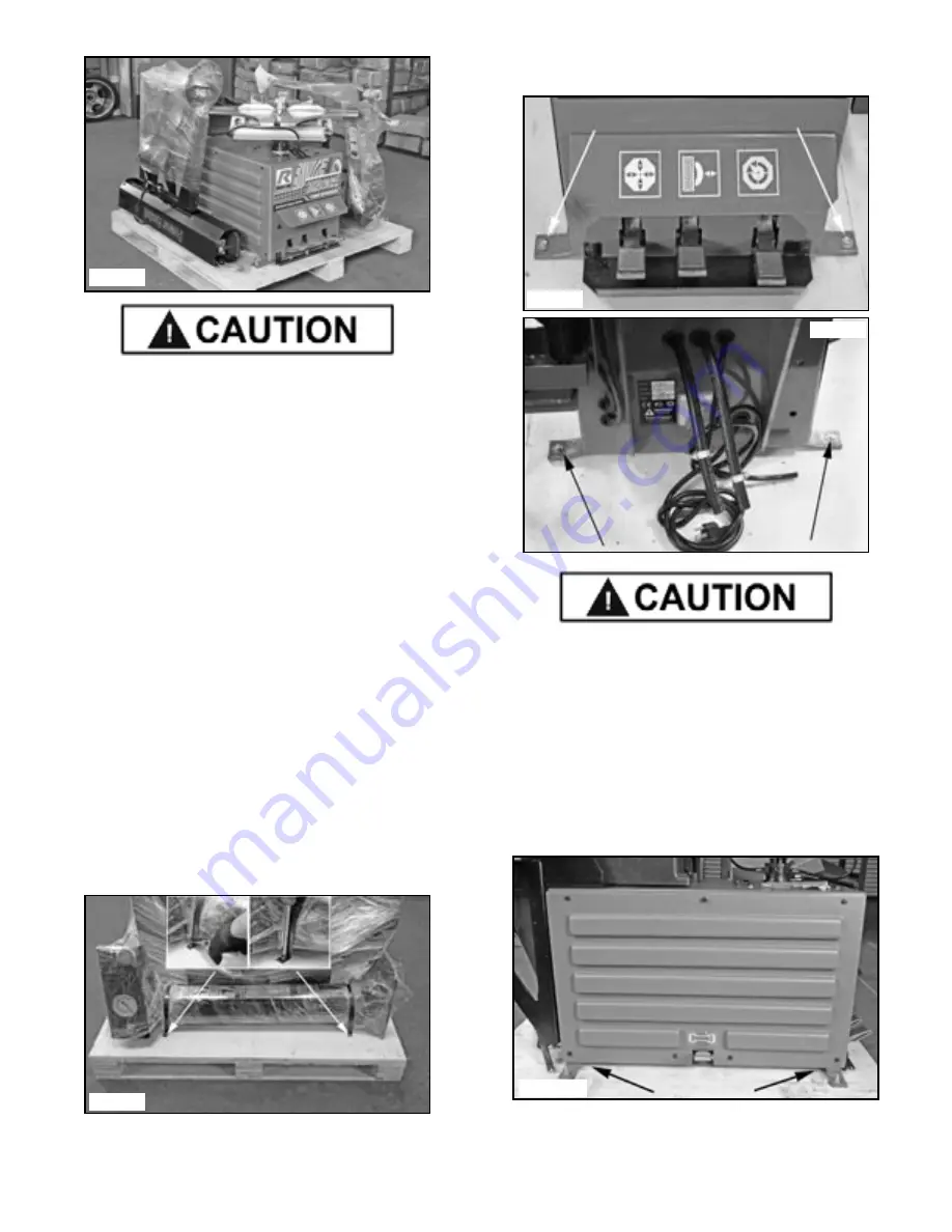
CAUTION!
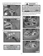
Secure the Air Tank / Assist Tower with shop crane/
forklift or personnel prior to cutting metal strapping
as Air Tank / Assist Tower may have shifted
during shipping. Be careful as banding may snap or
fly when tension is released.
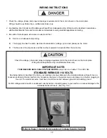
CAUTION!
DO NOT set the Tank/Tower on its base. Protect the
fittings on the Tower base when lifting. Protect the
air hose coming out of the base of the Assist tower
and the fittings on the back side of the Assist Tower.
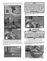
5. Either cut or unscrew the metal strapping holding the
Air Tower / Tank and Assist Tower to the pallet. Using a
fork lift or shop crane, remove both towers from the pallet
and set aside. Secure both towers so they can not fall.
(See Fig 6.7)
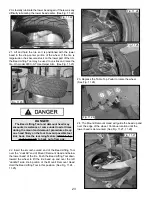
6. Remove the four front and rear Bolts and Nuts holding
the tire changer from the pallet. (See Figs. 6.8 - 6.9)
CAUTION!
Handling of the machine must be performed only
with an appropriate lifting device such as a forklift or
shop crane. Only personnel who are experienced and
qualified on material handling procedures should
handle any transportation or moving of machine
.
7. Using a shop crane or fork lift with lifting straps,
remove the Tire Changer from the wooden pallet. Use
only properly rated lifting straps under the Tire Changer
base. (See Fig. 6.10)
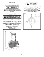
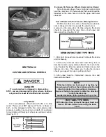
8. Locate the tire changer using the guidelines in
Section 7, page 11.
Fig. 6.9
Fig. 6.10
Fig. 6.8
Fig. 6.7
Fig. 6.6
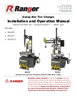
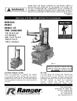
Summary of Contents for R980X
Page 39: ...39 ...
Page 48: ...48 ...
Page 49: ...49 RECORD ALL MAINTENANCE NOTES AND SERVICE HISTORY HERE ...
Page 50: ...50 TIRE AND WHEEL DATA ...