


12
SECTION 8
R980X /AT ASSEMBLY
Air Tank/ Tower Assembly
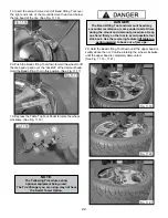
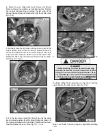
1. Remove the Tool Tray. (See Fig. 8.1)
3. Using a fork lift or other lifting device, lower the Tank/
Tower onto the base and align the holes. Take care not to
damage the fittings on the bottom of the Tank/Tower.
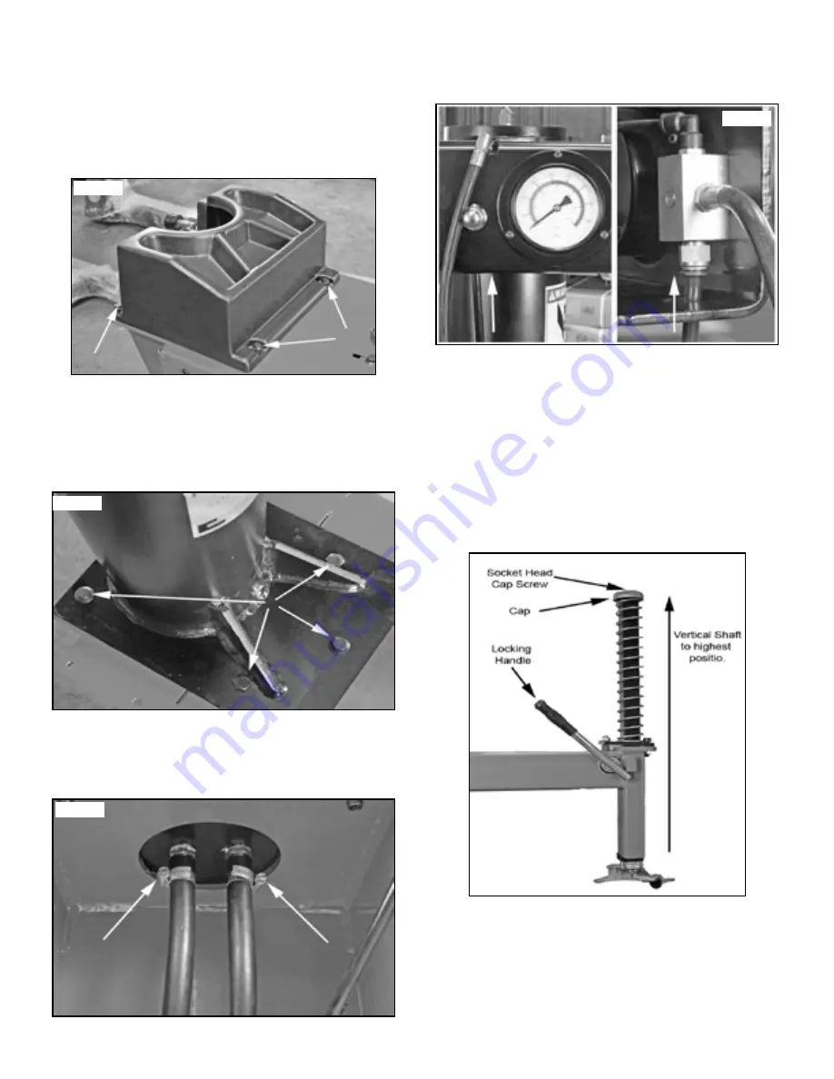
4. Attach the Tank / Tower assembly to the Base using
the five bolts on the Tower Base Plate. (See Fig. 8.2)
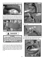
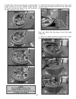
5. Connect the two large Air Lines coming out of the rear
of the Cabinet to the Two Barb Fittings on the under side
of the Air Tank / Tower using the supplied Hose Clamps.
(See Fig. 8.3)
6. Connect the other end of the Air Inflation Hose to the
Push to Connect Fitting inside the Air Inflation Box
Assembly. (See Fig. 8.4)
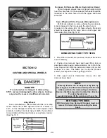
Swing Arm/Vertical Shaft/Mount-demount
Head Assembly
1. Raise the Vertical Shaft / Mount-demount Head
assembly to the highest position and lock it in place by
Pushing the Locking Handle Down.
2. Check the Socket Head Cap Screw on the Cap,
Tighten if necessary. (See Fig. 8.5)
3. Check the operation of the Vertical Shaft and the
Locking Handle.
(See Section 17, Page 34 for Lock adjustment details)
Fig. 8.1
Fig. 8.2
Fig. 8.3
Fig. 8.4
Fig. 8.5
Summary of Contents for R980X
Page 39: ...39 ...
Page 48: ...48 ...
Page 49: ...49 RECORD ALL MAINTENANCE NOTES AND SERVICE HISTORY HERE ...
Page 50: ...50 TIRE AND WHEEL DATA ...