INSTALLATION
1. Assemble the bench and chip trays according to the
diagram on page
7
. Tighten all fasteners securely.
2. After assembly, the bench should be leveled. The bench
may be bolted down with 3/8” concrete bolts or lag screws.
3. Unbolt the lathe from the shipping pallet and remove
any packing materials and protective wrapping. Lift the
lathe onto the bench.
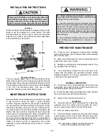
Always follow safe lifting practices when lifting heavy loads.
Use a forklift or crane only. Do not attempt to lift lathe unit
onto the bench without the use of material handling
equipment with a lifting capacity 400 pounds or greater.
4. Bolt the lathe to the bench with the hardware provided.
Tighten fasteners securely.
5. Remove any packing materials and protective wrapping
from the lathe and components.
6. Make sure the lathe is turned off. Plug lathe into a properly
installed and grounded outlet that matches the lathe plug.
IMPORTANT NOTE
Position the voltage selector switch at the rear of the unit to
the appropriate voltage setting before plugging the lathe into
outlet. Verify that the lathe plug and grounding-type
receptacle match.
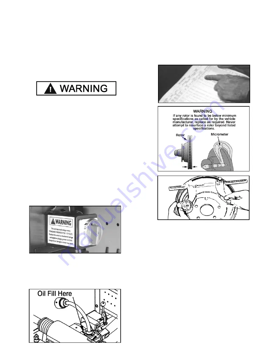
7. Remove the oil plug, insert the oil dipstick, and check oil
level. The lathe is shipped with the correct amount and
type of oil. Add oil as necessary to reach the correct mark
on the dipstick. Use only EP-80-90 gear oil. Oil level
should be checked often.
BRAKE ROTOR/DRUM INSPECTION
1. Before attempting any resurfacing, rotor and/or drum
inspection is necessary. Determine the manufacturer's
specifications from an approved specification guide.
2. Using a digital micrometer or other measuring tool, record
the thickness of the rotor or drum. Observe any deep scores
and gouges. This depth will also need to be recorded.
3. Determine if the total amount of material to be removed
will meet the manufacturer's minimum specifications. If any
rotor is found to be below minimum specifications as called
for by the vehicle manufacturer, replace as required.
BASIC OPERATION
To help you understand drum and rotor turning, read the
following that helps explain the features, operation and
principles of drum and rotor resurfacing.
Horizontal Spindle / Arbor
The spindle (horizontal main shaft) is motor driven and
turns the arbor (main rod with threaded tip) which the brake
drums or rotors are mounted on. When turning the drum or
rotor via the arbor and holding a cutting tool against the
braking surface, metal can be removed making the final
result a smooth finish that meets original factory
specifications. Smooth brake surfaces will extend the life of
the brake pads and increase brake operation efficiency.
8


