background image

8

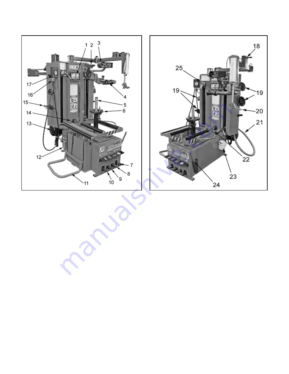
(1)  Video  Monitor

  —  Video  assist  displays  Lower  Bead 

Tools.

(2) Upper Bead Breaker Roller 

— Breaks Upper Bead.

(3) Control Pod

 —  Houses Hydraulic controls.

(4) Top Bead Assist Roller

 — Provides downward 

pressure during tire mounting operations.

(5)  Center  Post

  —  Provides  centering  and  clamping 

forces.

(6) Turntable

 — Provides platform and rotation of Rim and 

tire.

(7) Turntable Rotation Pedal 

— Controls the Rotation of 

the Turnable clock and counter clockwise.

(8)  Inflation  Pedal

  —  Controls  tire  inflation  and  pressure 

gauge.

(9) Too Head Control Pedal

 — Controls orientation of Tool 

Head.

(10)  Wheel  Lift  Control  Pedal 

—  Controls  operation  of 

Wheel lift- raises and lowers tire/rim.

(11) Wheel Lift Cradle 

— Support wheel during Lifting and 

lowering wheel. 

(12)  Air/Oil  Regulator/Dryer

  —  Regulates  Incoming  Air 

Pressure, Dries  and/or oils incoming air.

(13)  Air Tank

 — Air storage tank for inflation and “Turbo-

Blast”  bead sealing operation.

(14) Camera

 — Video assist for Lower Bead operations.

(15) Quick Nut

 — Locks the Rim to the turntable.

(16) Inflation Hose

 — Inflates the tire.

(17) Pressure Gauge Assembly 

— Displays the tire 

pressure, Releases tire pressure, stores Inflation Hose.

(18) Reversible Drop Center Tool Control 

— Pneumatic 

Control of Reversible Drop Center Tool height.

(19)  Tool-Storage  Pegs

  —  A  convenient  place  to  store 

Cones, Quick nut or other accessories.

(20)  Reversible Drop Center Tool

 —


Used to lift and posi-

tion tire bead correctly during mounting procedures.

(21) Turbo-Blast Hose Assembly

 — Used  to Seat bead 

with a powerful pneumatic blast.

(22)  Lower Bead Breaker Roller 

— Breaks Lower Bead.

(23)  Tire Lubricant Container 

— Convenient storage of 

Bead Lubricating solution and brush.

(24)  Tire Iron Tool / Storage  

— Convenient storage of 

Tire tools.

(25)  Tool Head 

—  Lifts upper and lower beads off of rim 

during demounting and mounting operations.

SECTION 5

DESCRIPTION OF PARTS

Summary of Contents for RX3040

Page 1: ...pped title passes to the purchaser upon receipt from the carrier Consequently claims for the material damaged in shipment must be made by the purchaser against the transportation company at the time s...

Page 2: ...s caused by ordinary wear abuse misuse shipping damage improper installation voltage or lack of required maintenance t damages resulting from purchaser s neglect or failure to operate products in acco...

Page 3: ...urable corrosion resistant stainless steel spools Auto shutdown technology Failure to follow danger warning and caution instructions may lead to serious personal injury or death to operator or bystand...

Page 4: ...6 Assembly Instructions 10 12 SECTION 7 Air Source 13 SECTION 8 Electrical Connections 14 SECTION 9 Control Overview 16 29 OPERATION SECTION 10 Wheel Inspection and Prep 30 32 SECTION 11 DemountingaT...

Page 5: ...all installation instructions t Make sure installation conforms to all applicable Local State and Federal Codes Rules and Regulations such as State and Federal OSHA Regulations and Electrical Codes t...

Page 6: ...e terminal This is for ground only 11 DANGER The motor on this machine contains high voltage Disconnect power at the receptacle before performing any electrical repairs Secure plug so that it cannot b...

Page 7: ...heel failure may result during inflation Explosion from failure may result in severe injury or death of the operator and bystanders Inflation ALWAYS be sure the bead opposite the tool head is in the d...

Page 8: ...air 13 Air Tank Air storage tank for inflation and Turbo Blast bead sealing operation 14 Camera Video assist for Lower Bead operations 15 Quick Nut Locks the Rim to the turntable 16 Inflation Hose Inf...

Page 9: ...Reservoir through this opening 32 Air Tank Pressure Gauge Assembly Displays the Air Tanks s pressure 33 Air Tank Air storage tank for inflation and Turbo Blast bead sealing operation 34 Air Tank Drai...

Page 10: ...PERFORMED ONLY WITH AN APPROPRIATE LIFTING DEVICE SUCH AS A FORKLIFT OR PALLET JACK ONLY PERSONNEL WHO ARE EXPERIENCED AND QUALIFIED ON MATERIAL HANDLING PROCEDURES SHOULD HANDLE ANY TRANSPORTATION OR...

Page 11: ...an specially trained and authorized operators are expressly forbidden to enter this area Choose a safe location that is in compliance with current work place safety regulations CAUTION KEEP THE ASSIST...

Page 12: ...Post 4 Place the Mounting cones and Quick Nut on the accessory hangers mounted on the sides of the machine 5 Place the Tire Lubricant Container Bracket and place it in the holes on the side panel Fil...

Page 13: ...ight side of the rear of the machine A 1 4 ID hose or pipe for connection to the machine is satisfactory Sufficient air pressure assures good performance See Fig 7 1 2 Adjust Pressure by turning knob...

Page 14: ...BEFORE ATTEMPTING TO INSTALL SERVICE RELOCATE OR PERFORM ANY MAINTENANCE DANGER GUARD AGAINST ELECTRIC SHOCK THIS EQUIPMENT MUST BE GROUNDED WHILE IN USE TO PROTECT THE OPERATOR FROM ELECTRIC SHOCK NE...

Page 15: ...ng 3 Be certain that adequate wire sizes are used and that t Service is of adequate amp rating t The supply line has the same electrical characteristics voltage cycles and phase as the motor t The lin...

Page 16: ...Wheel Lift will lower wheel to bottom position if started in raised position 3 By pushing and holding the pedal and feathering the pedal you can slow the decent or ascent of the wheel Use this method...

Page 17: ...lace the Shaft pin and Hair Pin CENTER POST FORWARD AND BACKWARD The Center post can be Adjusted front and backwards to align the Wheel Rim with the Bead Breaker Rollers and Hook and Tab Assist Arm 1...

Page 18: ...7 9 9 3 Pull UP on the Turntable Rotation Pedal to rotate counter clockwise See Fig 9 8 9 9 NOTE Table top rotation can be stopped at any time by removing your foot from the rotation pedal Normal tab...

Page 19: ...djustable using the Control Pod See Fig 9 12 9 13 CAUTION AFTER ANY ADJUSTMENTS ARE MADE TO THE BEAD BREAKER ROLLER ARMS LENGTHS THE TARGET LOCK END POSITION OF THE TOOL HEAD WILL NEED TO BE ADJUSTED...

Page 20: ...the release lever or raise the assembly to the highest point to release Push down on the Upper Bead Breaker Roller to lock it in place See Fig 9 15 Top Bead Assist Roller 1 The top Bead Assist Roller...

Page 21: ...anually 3 Out Target Lock Auto Locating 4 Hook or Tab Position UP AND DOWN 1 Use the Joystick on the Control Pod to raise and lower the Tool Head Assembly Up or Down See Fig 9 18 9 19 IN AND OUT MANUA...

Page 22: ...l Head Control Pedal and release See Fig 9 23 2 Each time the Tool Head Control Pedal is depressed the Tool Head will rotate See Fig 9 24 9 25 CAUTION ANY TIME THE TOOL HEAD IS CHANGED FROM THE STEEL...

Page 23: ...ngth of the Drop Center Shaft to the desired length Line up the Pin Holes and replace the Lock pin See Fig 9 27 2 To Operate the Drop Center Tool Push Up on the Joystick to move the Drop Center Tool u...

Page 24: ...24 2 Lifting or supporting the under side of the tire to help Center the Lower Bead into the Drop Center of the Rim when Mounting See Fig 9 30 Fig 9 30...

Page 25: ...se is used to inflate the tire after Bead Seating 1 The Inflation Hose is stored clipped to the Bottom of the Tire Pressure Gauge See Fig 9 33 CAUTION NEVER POINT NOZZLE TOWARDS YOURSELF OR OTHER PERS...

Page 26: ...Regulator regulates the incoming pressure and removes moisture from incoming air and oils the air that is sent to the Pneumatic Cylinders 1 Connect the incoming Air Source to the Air Oil Regulator usi...

Page 27: ...two to three drops are visible through the Oil Flow Site Glass when operating the Wheel Lift Water Reservoir 2 To Drain the Water Reservoir Unscrew the Drain plug 1 4 turn and then push up till all w...

Page 28: ...red plum the drain to an outside location or drain See Fig 9 43 Monitor 1 The Video Monitor will come on when the machine is power up Check that the Power button is on if Monitor fails to display an i...

Page 29: ...29 Fig 9 47 Fig 9 48...

Page 30: ...stem See Fig 10 1 Fig 10 1 CAUTION REVIEW IMPORTANT WHEEL MOUNTING INSTRUCTIONS ON PAGE 31 BEFORE PROCEEDING FAILURE TO DO SO MAY DAMAGE TIRE RIM OR TIRE CHANGER DANGER THERE ARE MANY PINCH POINT ON T...

Page 31: ...Narrow Side and Wide Side flanges 3 The tire must ALWAYS be demounted or mounted with the wheel positioned on the turntable with the Narrow Side facing upward and the deepest part of the Drop Center f...

Page 32: ...the Tool Head Arm and raise it to it s highest position 6 Press the Turntable Rotation Pedal and align the Centering Pin towards the front 6 o clock position This will ease the alignment of the Pin wi...

Page 33: ...ss the Wheel Lift Pedal again to lower the rim onto Turntable 6 Align a lug hole on the rim towards the front of the machine at 6 o clock position Slowly lower the Tire so that the Alignment Pin goes...

Page 34: ...earance to flip down the Upper Bead Breaker Roller assembly See Fig 11 7 11 Flip Down the Upper Bead Breaker Roller See Fig 11 8 12 Lower the Upper Bead Breaker Roller to within about an inch of the t...

Page 35: ...RIM AS THE UPPER BEAD BREAKER ROLLER WARNING KEEP HANDS CLEAR KEEP HANDS CLEAR OF ALL COMPONENTS OF THE TIRE CHANGER WHEN ROTATING TURNTABLE DURING MOUNTING PROCEDURES THERE ARE MANY PINCH OR CRUSH HA...

Page 36: ...rntable clockwise 21 Keep moving the Upper Bead Breaker Roller Down until the Upper Bead is into the Rim s drop Center See Fig 11 17 22 Pulse the Upper Bead Breaker switch down in small increments and...

Page 37: ...ead Control lower the Tool Head down to just above the rim See Fig 11 24 28 Then press the Target Lock button on the Tool Head Control Joystick and hold The Tool Head will extend from it s preset posi...

Page 38: ...pops under the hook See Fig 11 29 32 Continue rotating the tire and Pull Bead out See Fig 11 30 33 Continue Pulling the Bead up and then in See Fig 11 31 34 Until Upper bead pops off tire See Fig 11...

Page 39: ...s Drop Center See Fig 11 34 5 Raise Drop Center Tool until lower bead is in drop center See Fig 11 35 6 Push the Target Lock button and Hold the Tool Head Tab will extend to the preset position 1 4 fr...

Page 40: ...RNTABLE DURING MOUNTING PROCEDURES THERE ARE MANY PINCH OR CRUSH HAZARDS IF HANDS ARE KEPT IN CONTACT WITH THE MACHINE DURING DEMOUNTING ROTATION NOTE TABLE TOP ROTATION CAN BE STOPPED AT ANY TIME BY...

Page 41: ...e On these wheels the beads should be loosened at the valve hole on both upper and lower sides first SECTION 13 DEMOUNTING TUBE TYPE TIRES 1 After both tire beads are loosened lubricate the beads and...

Page 42: ...R DAMAGED WHEEL DAMAGED TIRES AND OR WHEELS MAY EXPLODE WARNING IF YOU DAMAGE THE TIRE BEAD DURING MOUNTING STOP REMOVE THE TIRE AND MARK IT AS DAMAGED DO NOT MOUNT A DAMAGED TIRE WARNING CHECK TIRE A...

Page 43: ...ower bead is below rim 3 Rotate Turntable until Lower Bead drops below top edge of Rim See Fig 14 4 4 If necessary for some stiff sidewall tires use the Upper Bead Breaker Roller to help push the down...

Page 44: ...Center Swing Arm Up and to the right out of the way WARNING KEEP HANDS CLEAR KEEP HANDS CLEAR OF ALL COMPONENTS OF THE TIE CHANGER WHEN ROTATING TURNTABLE DURING MOUNTING PROCEDURES THERE ARE MANY PIN...

Page 45: ...icant to the tube 4 Insert the tube into the tire paying careful attention not to pinch the tube 5 Mount the Upper Bead as indicated in Section 14 Stop the Rotation periodically This allows you to ins...

Page 46: ...GAUGE FOR PROPER OPERATION ACCURATE PRESSURE READINGS ARE IMPORTANT TO SAFE TIRE INFLATION REFER TO THE OPERATING MAINTENANCE SECTION OF THIS MANUAL FOR INSTRUCTIONS DANGER THE CLIP ON AIR CHUCK ON T...

Page 47: ...upper edge of the wheel Be sure tires top bead is over the bottom of the valve stem See Fig 16 6 WARNING THIS DEVICE ACTS AS A RESTRAINT DEVICE ONLY IT WILL NOT PROTECT OPERATORS IN THE EVENT OF CATA...

Page 48: ...e air flow into the tire to assist with bead seal After bead seal is achieved remove the chuck and reinstall the valve core TIRE INFLATION The unit is equipped with a pressure limiter regulator to ass...

Page 49: ...seat Keep hands arms and entire body away from tire during this procedure Tire beads should move outward and pop into their bead seat position as pressure inside the tire increases If this does not ha...

Page 50: ...E SERIOUS INJURY OR DEATH TO OPERATOR OR BYSTANDER MIS MATCHED TIRES AND WHEELS NEVER ATTEMPT TO MOUNT MIS MATCHED TIRES AND WHEELS MIS MATCHED TIRE AND WHEEL COMBINATIONS CAN EXPLODE CAUSING PERSONAL...

Page 51: ...60 PSI ALWAYS USE A SAFETY CAGE AND AIR HOSE WITH A CLIP ON CHUCK AND IN LINE VALVE THE HOSE MUST HAVE ENOUGH LENGTH BETWEEN THE CHUCK AND THE OPERATION IN LINE VALVE TO ALLOW THE OPERATOR TO OUTSIDE...

Page 52: ...normally Follow detailed inspection and testing procedures as specified for various components at regular intervals t Replace any damaged or missing safety decal s They are available from the factory...

Page 53: ...olvent every month SEMI ANNUALLY t Every six months add about 250g of 26 weight gear oil to the gearbox ANNUALLY t Replace hydraulic fluid annually with AW32 hydraulic fluid use a clean funnel to refi...

Page 54: ...UT TAG OUT the machine while performing the Limit switch adjustment WARNING KEEP HANDS CLEAR KEEP HANDS CLEAR OF ALL COMPONENTS OF THE TIRE CHANGER WHEN ROTATING TURNTABLE DURING MOUNTING PROCEDURES T...

Page 55: ...ng 11 Lower the Tool Head to gauge the distance from the Tab Side of the Tool Head to the Lower Rim Edge See Fig 17 8 12 Raise the tool head above the Rim and repeat adjustment procedure if necessary...

Page 56: ...matically Both gauges should read 60 PSI 5 PSI 5 If the pressure exceeds 60 PSI adjust the knob on the regulator by lifting the locking cover and turning COUNTERCLOCKWISE After adjustment is made secu...

Page 57: ...57 DRIVE BELT ADJUSTMENT 1 Remove right side access panel 2 Inspect the Drive Belt for cracking and wear and replace as necessary Adjust the Belt deflection to 3 8 1 2 See Fig 17 12 Fig 17 12...

Page 58: ...58 CRITICAL SAFETY WARNINGS...

Page 59: ...59 CRITICAL SAFETY WARNINGS...

Page 60: ...Position Automatic Mount Demount Inflation System Standard Inflation Pressure Regulator Limiter Standard Traveling Drop Center Top Mount Helper Standard Top Power Assist Bead Roller Standard Water Fil...

Page 61: ...61 Parts Breakdowns...

Page 62: ...62...

Page 63: ...63...

Page 64: ...64...

Page 65: ...65...

Page 66: ...66...

Page 67: ...67...

Page 68: ...68...

Page 69: ...69...

Page 70: ...70 T I R E C H A N G E R X Electric Schematic Diagrams 12...

Page 71: ...71 T I R E C H A N G E R All electric appliances must be installed by electricians 13...

Page 72: ...control 6 Rotary valve of working head under three position five way control 7 Column switching normal valve under manual control 8 Anti blowout inflation valve under pedal control 9 Pressure regulat...

Page 73: ...cylinder under 4 3 electromagnetic control 6 Tire shovel wheel cylinder under 4 3 electromagnetic control 7 Working head lifting cylinder under 4 3 electromagnetic control 8 Working head back and fort...

Page 74: ...Parts Or Service Contact BendPak Inc Ranger Products 1645 Lemonwood Dr Santa Paula CA 93060 Tel 1 805 933 9970 Toll Free 1 800 253 2363 Fax 1 805 933 9160 www bendpak com www rangerproducts com PN 590...

Reviews: