12
BALANCING INSTRUCTIONS
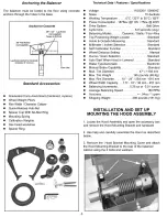
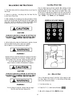
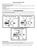
1. First determine which mounting method you will use for
the wheel.
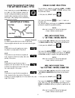
2. Select a centering / mounting cone that best fits the
center hole of the wheel.
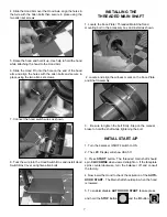
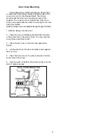
3. After installing the necessary mounting hardware, lift the
wheel onto the threaded shaft and slide it back against the
arbor hub. It will be necessary to lift the wheel slightly when
positioning the cone in the center of the wheel hole.
CAUTION!
DAMAGE CAUSED BY STRIKING OR HITTING THE
QUICK-NUT WITH HAMMER, TIRE IRON OR HEAVY
OBJECT IS NOT COVERED UNDER WARRANTY!
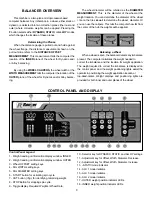
4. While holding the wheel and hardware in position, thread
the Quick-Nut over the arbor and secure tightly.
Never hammer or hit the Quick-Nut to tighten.
WARNING!
Always make sure that the Quick-Nut engages the arbor
threads by at least four (4) full turns. It helps to spin the
wheel while at the same time tightening the Quick-Nut.
Never exceed weight capacity of balancer!
Never hammer or strike the Quick-Nut to tighten.
CAUTION!
DAMAGE CAUSED BY STRIKING OR HITTING THE
QUICK-NUT WITH HAMMER, TIRE IRON OR HEAVY
OBJECT IS NOT COVERED UNDER WARRANTY!
WARNING!
Do not attempt to balance wheels that are larger
than the machine was designed for.
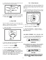
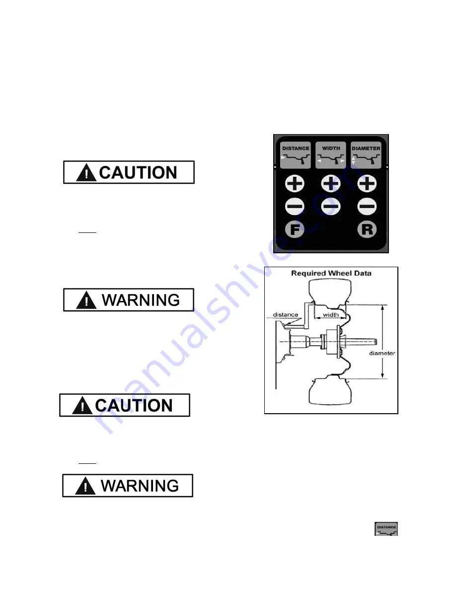
Inputting Wheel Data
Prior to balancing any wheel, specific data relating to that
particular wheel must be entered into the computer. If the
data displayed on the screen does not match that of the
wheel you are attempting to balance then the wheel will not
be accurately balanced. The three data requirements are;
“-A-” Offset, “-L-” Width and “-d-” Diameter.
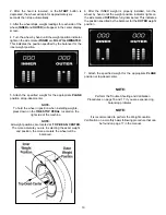
WHEEL DATA KEY BOARD
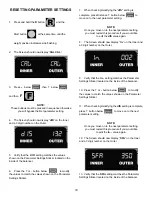
dis - Wheel Offset
This is the distance between the side of the balancer and
the inner edge of the wheel. To enter Wheel Offset data
refer to the instructions below.
1. Turn the machine on.
2. Press the
+
or
-
button below Distance .
3. -
A-
will be displayed in the INNER window.


