background image


R80EX Tire Changer 

22


P/N 5900087 — Rev. B — Jan. 2020 

Connecting to Pressurized Air 

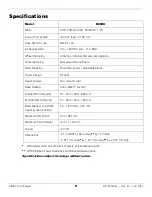
The Tire Changer requires a 15 to 25 CFM Air Source with an operating air pressure of 140 to 165 PSI 

/ 9.6 to 11.4 BAR. 

Important

:  The Tire Changer uses pneumatic and electrical energy; if your organization has 

Lockout/Tagout policies, implement them once the unit is connected to the air source. 

The air lines going out of the Regulator/Filter and Lubricator come connected and ready for use; 

no 

installation or adjustment is required when you receive the Tire Changer

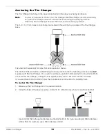
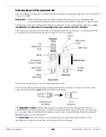
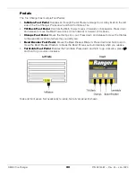
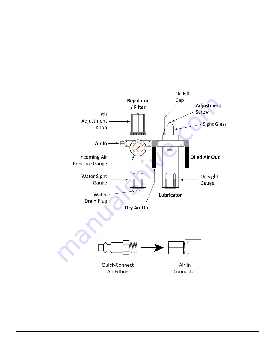
The incoming air source connects to the Tire Changer via the Air In connector on the Regulator/Filter. 

You need to provide a fitting for the Air In connector; it is not supplied. 


Drawing not necessarily to scale. Not all components shown. 

The following drawing shows a quick-connect air fitting that connects to the Air In connector. The 
quick-connect air fitting is 

not

 supplied with the Tire Changer. 


The 

Regulator / Filter

 controls the air pressure coming into the Tire Changer and removes 

contaminants from the incoming air. It includes a gauge that shows the air pressure of the incoming 

air. If you see water in the Water Sight Gauge, you can drain it using the Water Drain Plug. Refer to 

Maintenance

 for more information. 

The 

Lubricator

 puts pneumatic oil, for lubrication, into the incoming air that reaches it. This 

lubricated air is routed to pneumatic components of the Tire Changer. 


Summary of Contents for R80EX

Page 1: ...and engineered in Southern California USA Made in China DANGER Read the entire contents of this manual before using this product Failure to follow the instructions and safety precautions in this manual can result in serious injury or death Make sure all other operators also read this manual Keep the manual near the product for future reference By proceeding with installation and operation you agre...

Page 2: ...our nearest BendPak Ranger dealer or visit bendpak com support warranty Go to bendpak com support register your product and fill out the online form to register your product be sure to click Submit Safety Your product was designed and manufactured with safety in mind Your safety also depends on proper training and careful operation Do not set up operate maintain or repair the unit without reading ...

Page 3: ...t You can always find the latest version of the manual for your product on the Ranger website DANGER Be very careful when setting up operating maintaining or repairing this equipment failure to do so could result in property damage product damage injury or in very rare cases death Make sure only authorized personnel operate this equipment All repairs must be performed by an authorized technician D...

Page 4: ...re using your new product Do not set up or operate the product until you are familiar with all operating instructions and warnings Do not allow anyone else to operate the product until they are also familiar with all operating instructions and warnings WARNING There are many moving parts on a Tire Changer keep clear of these moving parts and the Tire being changed In particular when inflating a Ti...

Page 5: ...ely worn parts decals or warning labels Symbols Following are the symbols that may be used in this manual DANGER Calls attention to a hazard that will result in death or injury WARNING Calls attention to a hazard or unsafe practice that could result in death or injury CAUTION Calls attention to a hazard or unsafe practice that could result in personal injury product damage or property damage NOTIC...

Page 6: ... Jan 2020 Components The following graphic identifies the main components of the R80EX Tire Changer Front and right side views Components on left side and rear not visible including the Turbo Blast System and the Regulator Filter Lubricator ...

Page 7: ...oves the Clamps to the opposite position If Clamps are in moves them out if Clamps are out moves them in Bead Breaker Foot Pedal Moves the Bead Breaker Blade in release to retract Turntable Foot Pedal Rotates the Turntable Press down and hold to rotate the Turntable clockwise press up and hold to rotate the Turntable counter clockwise Regulator Filter and Lubricator Control and route the incoming ...

Page 8: ...d is seated during mounting When you break the Bead you move the Tire Bead out of the location where it was seated breaking the Bead is required before you can take the Tire off the Wheel Q Can I break the Bead without fully deflating the Tire first A No do not do this Always fully deflate a Tire before attempting to break its Bead The air pressure energy in a Tire even if not fully inflated can b...

Page 9: ...sign Tilt back Assist Towers Two left and right Bead Sealing Turbo Blast system Internal Rim Clamping 13 34 in 305 864 mm External Rim Clamping 10 30 in 254 762 mm Bead Breaker Tire Width Capacity Demounting 1 5 18 in 38 457 mm Maximum Rim Width 15 in 381 mm Maximum Tire Diameter 47 in 1 194 mm Sound 70 dB Dimensions 91 in wide by 66 in deep by 79 in high 2 311 mm wide by 1 677 mm deep by 2 007 mm...

Page 10: ... the necessary Tools 3 Find an appropriate Location 4 Make sure there is adequate Clearance around and above 5 Unpack the Tire Changer 6 Install the Storage Cabinet 7 Install the Bead Breaker Mechanism 8 Anchor the Tire Changer 9 Connect to Power Requires a licensed Electrician 10 Connect to pressurized Air 11 Prepare the Lube Bucket 12 Grease the Assist Tower Posts 13 Test the Tire Changer 14 Rev...

Page 11: ...151 personal protective equipment at all times when installing the Tire Changer leather gloves steel toed work boots eye protection back belts and hearing protection Use caution when unpacking the Tire Changer from its shipping container and setting it up The Tire Changer is heavy and the weight is not evenly distributed dropping or knocking over the unit may cause equipment damage and personal in...

Page 12: ...ntaminants such as oil grease water dirt brake lathe chips and so on Contaminants degrade the performance of the Tire Changer and may cause components to wear out more quickly Danger When a Tire is on the Tire Changer especially during inflation you need to keep everyone far away from it Only the Operator should be within 30 feet of the Tire Changer when it is in use Do not set up the Tire Changer...

Page 13: ...ING The Clearance values shown below allow enough space to operate the Tire Changer For safety purposes only the Operator should be within 30 feet of the Tire Changer while it is in use Top view Not necessarily to scale Not all components shown The additional space at the front of the Tire Changer is needed to move Tires to and from the Tire Changer ...

Page 14: ...UTION Ranger recommends having at least two people lift the Cover off it is heavy and awkward If it is dropped or falls it could cause injury or equipment damage 3 Remove the Accessory Box 4 Move the uninstalled Storage Cabinet and Bead Breaker Mechanism out of the way 5 Remove the bolts that hold the Tire Changer to the Pallet 6 Move the Tire Changer off the Pallet then move it to the desired loc...

Page 15: ...of the Left Assist Tower Make sure to take off both washers 2 Move the Storage Cabinet into place on the left side of the Left Assist Tower with the holes in the side of the Storage Cabinet lined up with the holes in the side of the Left Assist Tower 3 Insert the two Socket Head Cap Screws Lock Washers and Flat Washers that you just removed through the holes in the side of the Storage Cabinet and ...

Page 16: ...s The Arm Pin part of the Arm Pin Bracket Assembly goes through the Arm Pin Hole The Return Spring gets stretched out and hooks to the Return Spring Hole The Cylinder Shaft gets extended and goes through the Pivot Pin Once the Bead Breaker Mechanism is installed you need to attach the Blade Tension Spring between the bottom of the Bead Breaker Mechanism and the small hole at the bottom of the Bead...

Page 17: ...ut the Arm Pin Bracket Assembly back into place then securely tighten the Socket Head Cap Screw and washers on the side of the Assembly using a 6 mm hex key 5 Switching to the Cylinder Shaft and the Pivot Pin adjust the Pivot Pin in the Bead Breaker Mechanism so that the squared off side is facing away from the Tire Changer This is required Includes top and side views Not necessarily to scale Not ...

Page 18: ...Head Cap Screw Side view Blade Tension Spring goes on the underside of the Bead Breaker Mechanism Not necessarily to scale Not all components shown 3 Tighten the Lock Nut down towards the Socket Head Cap Screw so that the closed end of the Spring is secure between them 4 Tighten the Socket Head Cap Screw into the Bead Breaker Mechanism use a 5 mm hex key 5 Extend the Blade Tension Spring and put t...

Page 19: ...cale Not all components shown The Anchor Bolts sometimes called Wedge Anchors mentioned in the following procedure are not supplied with the Tire Changer You could for example use 3 8 in diameter by 3 in long Anchor Bolts to secure the Tire Changer drilling the hole approximately 2 5 in 63 5 mm into the Concrete If you use different Anchor Bolts follow the manufacturer s instructions for installin...

Page 20: ...ammer or mallet the Anchor Bolt should only go into the hole part of the way this is normal If the Anchor Bolt goes all the way in with little or no resistance the hole is too wide Once past the hole in the base the Anchor Bolt eventually stops going down into the hole as the Expansion Sleeve contacts the sides of the hole this is normal 5 Hammer or mallet the Anchor Bolt the rest of the way down ...

Page 21: ...you void your warranty and put everyone who uses the Tire Changer in danger of injury or in rare cases death Additional electrical information Make sure wiring is done in accordance with National Electric Code NEC and local codes and standards covering electrical apparatus and wiring Operation with no Ground can damage electronics and could create a shock hazard You must ground the unit Damage cau...

Page 22: ... connector on the Regulator Filter You need to provide a fitting for the Air In connector it is not supplied Drawing not necessarily to scale Not all components shown The following drawing shows a quick connect air fitting that connects to the Air In connector The quick connect air fitting is not supplied with the Tire Changer The Regulator Filter controls the air pressure coming into the Tire Cha...

Page 23: ...g Using non approved Tire Lubricant could corrode the Wheel or cause Tire Wheel slippage and vibration issues Be sure to use enough Tire Lubricant without using too much The point of Tire Lubricant is to temporarily reduce the friction between the Tire Bead area and the Rim What you are looking for is a Tire Lubricant that is slippery when wet but not slippery once dried If you notice excessive am...

Page 24: ...based grease that includes molybdenum and graphite For example Extreme Pressure Moly Graph Multi Purpose Grease from CRC Sat Lube CAUTION The lithium based grease for greasing Assist Tower Posts is not a Tire Lubricant Do not use it to lube Tires Once the Assist Tower Posts are greased up try not to lean on or touch them this uses up the grease faster The following drawing shows the grease locatio...

Page 25: ...damage to the Tire and the Wheel BendPak Ranger recommends using Lube that is recommended by the manufacturer of the Tire you are changing Test the Tool Arms on the Assist Towers Manually move each Tool Arm separately from side to side Use the Assist Tower Controls to raise and lower the Tool Arms they move up and down together If the Tool Arms can do these things they are working correctly Change...

Page 26: ...ontact the manufacturer Never exceed the maximum allowed inflation pressure of a Tire Instead inflate Tires to their recommended Tire pressure which can usually be found in the door jamb of the Vehicle or in the Owner s Manual Make sure the Tire is restrained for inflation either internally clamped held down by the Restraint Cone or in a Tire Inflation Cage such as the RIC 4716 4 Bar Tire Inflatio...

Page 27: ...llation and Operation Manual before using the Tire Changer Make a visual inspection of the Tire Changer before each use Do not operate the Tire Changer if you find any issues Instead take it out of service then contact your dealer visit bendpak com support or call Bendpak Ranger at 805 933 9970 Always identify and correctly match the Tire and Rim diameters of the Tires you are mounting they must m...

Page 28: ...e Turntable clockwise Press down and hold down the Turntable Foot Pedal To rotate the Turntable counter clockwise Press up and hold up the Turntable Foot Pedal Clamp Mechanism Each Clamp Mechanism includes a Clamp and two Clamp Adjustment Knobs The Clamp Mechanism moves in and out to clamp Wheels either externally or internally External and Internal clamping refer to the location of the Clamp in r...

Page 29: ... Wheel over the Clamps then press down on the Clamps Foot Pedal to move the Clamps out until the Wheel is being firmly held in place Note The Clamps Foot Pedal works as follows If the Clamps are in the center of the Turntable all the way in pressing down and then releasing the Clamps Foot Pedal moves them all the way out If the Clamps are all the way out pressing down and then releasing the Clamps...

Page 30: ...he Main Tower back if it is forward or forward if it is back Clamps Foot Pedal Moves the Clamps in or out Press down and release to move the Clamps to the opposite location of where they currently are Bead Breaker Foot Pedal Moves the Bead Breaker Blade in Press down and hold down to move the Bead Breaker Blade in to break the Bead Moves out automatically when you release Turntable Foot Pedal Rota...

Page 31: ...to hold the Air Chuck in place during inflation WARNING Never hold the Air Chuck while you are inflating a Tire This leaves you close to the Tire which could result in injury if there is a problem during inflation Threads Store the Air Chuck here using the self gripping clip Front view Not necessarily to scale Not all components shown To see the pressure in a Tire Attach the Air Chuck to the Tire ...

Page 32: ...ent Handle in and out Control Button When pressed on the outside locks the Shaft and Slide at their current positions When pressed on the inside unlocks the Shaft and Slide Adjustment Handle Moves the Slide in and out Shaft Cap Moves the Mount Demount Head down Do not grab the Shaft Spring or the part of the Shaft just above the Mount Demount Head they are not good options for controlling the Shaf...

Page 33: ...udes plastic inserts on the inside to avoid damaging Rims The following drawing shows the location of the Demount and Mount Lips and demount mount locations for Tire Beads Side view Set Screws on other side Not necessarily to scale Not all components shown The Demount Lip and Mount Lip work as follows During demounting The Tire Bead goes over the Demount Lip and under the Mount Lip During mounting...

Page 34: ... Blade Handle when the Bead Breaker is moving After positioning the Bead Breaker Blade move away from the Bead Breaker and make sure the area is completely clear before pressing the Bead Breaker Foot Pedal The main parts of the Bead Breaker are Bead Breaker Mechanism Moves in and out under the control of the Bead Breaker Foot Pedal Moves with great force make sure you are completely clear of the B...

Page 35: ... the Bead Breaker Mechanism over until you can see the other hole then put the Adjustment Pin into the other hole Bead Lifting Tool Use the Bead Lifting Tool to pull the Tire s Bead up and over the Mount Demount Tool to help demount the Tire You can also use the Bead Lifting Tool to push down the Tire s Bead to the left of the Mount Demount Head during the mounting of a Tire The Bead Lifting Tool ...

Page 36: ...o the Pressurized Air Tank When closed no air can get into the tank Pressure Relief Valve Releases air pressure from the tank if the pressure gets too high Hose Moves the pressurized air from the tank to the Nozzle Nozzle Where the pressurized air comes out DANGER Use extreme care with the Turbo Blast Bead Sealing System You could cause product damage personal injury or death Never point the Nozzl...

Page 37: ...top Bead during mounting Upper Assist Arm Holds two Tools and the Controls The two Tools are Restraint Cone Used in two ways First when mounting a Tire use the Restraint Cone to push the Tire down helpful when clamping a Wheel externally Second when inflating a Tire use to hold the Wheel in position on the Turntable Assist Tool Used to hold down the top Bead during mounting Travels with the Tire I...

Page 38: ...ower Arms up and down together Lock Button Locks the Lower Roller Rod Bead Roller Helper Disc The Knob lets you switch between the two Tools The Bead Roller holds down the top Bead during mounting The Helper Disc holds up the bottom Bead during demounting The Lower Assist Arm Knob lets you control how far back the Lower Assist Arm can swing back Upper and Lower Roller Rods Hold down the top Bead d...

Page 39: ...tances if you find damage you might want to discuss that damage with the owner of the Vehicle and or photograph the damage If you work in a shop talk to your Supervisor regarding policies in this area Damaged Wheels and Tires are dangerous to work with If you are not sure whether a Wheel or Tire is too damaged to work with talk to your Supervisor Understand Performance Wheels Before servicing perf...

Page 40: ...n the rest of the Tire Performance Wheels on some Vehicles including Corvette BMW and Lamborghini Diablo have a pressure sensor strapped to the Wheel opposite the Valve Stem On these Wheels the Beads should be loosened at the Valve Stem on both sides first before breaking the Beads on the rest of the Tire Be mindful of the TPMS sensor when breaking a Tire s Bead demounting a Tire and mounting a ne...

Page 41: ... on the Turntable The Tire Changer supports both Internal and External Clamping Make sure to put the Narrow side of the Tire facing up 4 Demount the Tire Once the Bead is broken you still have to slide both Beads over the top Rim of the Wheel to get it fully off Once the Tire is demounted from the Wheel you can move it out of the way and then mount the new Tire 5 Mount the new Tire Mounting a Tire...

Page 42: ...to cut out or pull out the old Valve Stem then install the new Valve Stem This should be done after the old Tire has been demounted but before the new Tire is mounted There is a tool called a Valve Stem Installer Remover Tool sometimes Valve Stem Puller Remover Tool that can be used to both remove an old Valve Stem and install a new Valve Stem This tool is not the same tool as the Valve Core Tool ...

Page 43: ...remove the Valve Core If a Tool is not available you may be able to use needle nose pliers If you are going to use the same Valve Stem with the new Tire you are going to mount keep the Valve Core you just took out BendPak Ranger recommends installing a new Valve Stem when you mount a new Tire 3 Make sure all of the air comes out of the Tire WARNING Do not proceed with any other Tire changing activ...

Page 44: ...ves steel toed work boots back belts hearing protection and ANSI approved eye protection safety glasses face shield or goggles 2 Check the Tire again to make sure it is fully deflated 3 Check both sides of the Tire to make sure all Wheel weights from balancing have been removed If they have not remove them CAUTION Breaking the Beads of a Tire with Wheel weights could damage the Tire Changer and or...

Page 45: ...oes not fully move the Bead out of the Bead Seat adjust the Blade a little bit one way or the other and then repeat Steps 10 and 11 It may take several attempts to break the Bead 13 When the Bead is broken at the first spot rotate the Tire 180 and break the Bead at that location Every Tire is different With some Tires the entire Bead on one side could be broken with the first use of the Bead Break...

Page 46: ...ts back belts hearing protection and ANSI approved eye protection safety glasses face shield or goggles 2 Identify the Narrow side of the Tire this side goes up 3 Determine which clamping method you are going to use and move the Clamps to the starting position for that clamping method If you are clamping externally move the Clamps all the way out If you are clamping internally move the Clamps all ...

Page 47: ...r gloves steel toed work boots back belts hearing protection and ANSI approved eye protection safety glasses face shield or goggles 2 Verify that the Tire s Beads are broken all the way around and on both sides of the Tire 3 Apply Tire Lubricant to both the top and bottom Tire Beads and the top Rim This helps slide the Beads over the Rims more easily 4 Move the Mount Demount Head into position ver...

Page 48: ...ntinue holding the Bead Lifting Tool 9 Press down and hold down the Turntable Foot Pedal the Turntable begins turning clockwise Note If you have difficulty getting the Turntable to move clockwise release the Turntable Foot Pedal keep hold of the Bead Lifting Tool and then press up on the Turntable Foot Pedal for few seconds to move the Turntable counterclockwise then press down again to move clock...

Page 49: ...ssarily to scale Helper Disc location is adjustable 15 Push the Bead Lifting Tool towards the middle of the Wheel in an arc pulling the bottom Bead over the Demount Lip of the Mount Demount Head 16 While continuing to hold the Bead Lifting Tool press down and hold down the Turntable Foot Pedal to move the Turntable clockwise Watch the bottom Bead to make sure it is being pushed over the top of the...

Page 50: ...RNING Do not mount a Tire on a Wheel until you yourself have positively identified and correctly matched the Tire and Rim diameters If you try to seat a Tire Bead on a mismatched Wheel and Tire by inflating it the Tire Bead may break with explosive force which could result in serious injury or death More information is available in OSHA standard 29 CFR 1910 177 Servicing Multi Piece and Single Pie...

Page 51: ...S and adjust the Tire if necessary Do not damage the sensor Check for yellow and red dots If found line them up with the appropriate locations on the Tire Make sure the Tire is fully deflated When mounting a Tire mount the bottom Bead first over the top of the Rim then the top Bead also over the top of the Rim To mount a Tire 1 Make sure you are wearing OSHA approved publication 3151 personal prot...

Page 52: ... Bead over the Mount Lip and under the Demount Lip Side view Not necessarily to scale 10 Position the Assist Tool if desired to the left of the Mount Demount Head about 20 of the total distance around the Tire with it pushing down on the Sidewall of the Tire Then position the Bead Roller if desired to the left of the Mount Demount Head with it also pushing down on the Sidewall of the Tire Top view...

Page 53: ...to stop the Turntable then press up on the Turntable Foot Pedal to move the Turntable counterclockwise Make any necessary adjustments and then proceed Eventually the top Bead slips under the Rim How long this takes can vary based on the Tire you are mounting Some Tires are more difficult than others CAUTION Do not use excessive force If the Turntable slows and then stops while you are holding down...

Page 54: ...vered separately below CAUTION The inflation process can produce noise Wear ear protection when inflating a Tire WARNING Do not exceed the maximum air pressure specified by the Tire manufacturer This increases the chances that the Tire could explode causing injury or even death to the Operator and bystanders Use the Pressure Gauge on the Tire Changer to monitor the air pressure in the Tire you are...

Page 55: ...ire This leaves you close to the Tire which could result in injury if there is a problem during inflation 4 Press and hold down the Inflation Foot Pedal for a second or two then release Air goes into the Tire and seals the Bead Bead Sealing takes very little air pressure anywhere from 0 to 3 psi which you can monitor on the Pressure Gauge You know the Bead is sealed when you no longer hear the sou...

Page 56: ...uires 7 psi or above Some Beads are hard to seat but never exceed 40 psi to seat the Bead After a few seconds you should hear a pop as the Beads are seated 4 Release the Inflation Foot Pedal 5 When the Beads on both sides of the Tire are seated remove the Air Chuck from the Valve Stem and reinstall the Valve Core 6 If the amount of air pressure it takes to seat the Beads exceeds the manufacturer s...

Page 57: ...ter could result in the Tire exploding which could injure or kill bystanders or the Tire Changer Operator To inflate a Tire 1 Verify that both the Beads on both sides of the Tire are sealed and seated 2 Verify that the Valve Core has been put back in 3 Make sure the Tire is restrained either internally clamped held down by the Restraint Cone or in a Tire Inflation Cage Do not inflate a Tire if it ...

Page 58: ... for instructions Weekly Check the oil feed rate of the Lubricator It should be 1 to 2 drops per use of a pneumatic component If it is above or below this level you need to adjust it Refer to Check the Oil Feed Rate and Adding Oil for instructions Weekly Check the amount of pneumatic oil in the Lubricator reservoir If it is under one half 50 full add oil Refer to Check the Oil Feed Rate and Adding...

Page 59: ...reservoir is one quarter 25 or more filled with water you need to drain it 2 Disconnect the incoming air at the Air In connector WARNING Make sure to disconnect the incoming air and make sure it cannot be reconnected until you are done draining the water from the Regulator Filter If the incoming air is reconnected during the procedure it could damage the Regulator Filter the Tire Changer and possi...

Page 60: ...ou press down on the Clamps Foot Pedal Your goal is for 1 or 2 drops to come out each time 3 If you are getting fewer than 1 or 2 drops turn the Adjustment Screw counter clockwise using a small flat head screwdriver then press the Clamps Foot Pedal again to check the output 4 If you are getting more than 1 or 2 drops turn the Adjustment Screw clockwise then press the Clamps Foot Pedal again to che...

Page 61: ...er to Wiring Information for additional information No air comes out of the Air Hose when you step on the Inflate Foot Pedal Make sure the unit is correctly connected to a working incoming air source It is difficult to secure Tires when clamping externally Use the Restraint Cone to press the Tire down so the Clamps correctly grab the Rim of the Wheel The Pressure Gauge is not working correctly Che...

Page 62: ...reen Yellow the European color code The Green Yellow wire can sometimes appear almost all Green with very little yellow This is fine Important To connect the three exposed wires to an appropriate Plug or to hard wire them have your Electrician follow the electrical codes for the country in which you are using the unit and any local electrical codes If you are using the unit in the United States fo...

Page 63: ...R80EX Tire Changer 63 P N 5900087 Rev B Jan 2020 Labels ...

Page 64: ...R80EX Tire Changer 64 P N 5900087 Rev B Jan 2020 ...

Page 65: ...R80EX Tire Changer 65 P N 5900087 Rev B Jan 2020 ...

Page 66: ...R80EX Tire Changer 66 P N 5900087 Rev B Jan 2020 Parts Cabinet Part Number Description 101 Breaker arm pin shaft 102 Breaker arm pin baffle 103 SHCS M6 x 16 104 Washer Φ6 flat 105 Washer φ6 splick lock ...

Page 67: ...2 Washer φ8 splick lock 123 Hexagon socket head screw M16 x 40 124 SHCS M6 x 10 125 STS ST5 5 x 25 126 Earth wire logo 127 Scutcheon 128 Cup head rivet 129 5327308 Side wall 130 5327307 Plastic foot pad 131 Hexagon headed bolt 132 Washer 133 Waterproof via coil nut M20 134 Chassis weldment 135 5327593 Side cover 136 Cross slotted large flat head screw M6 x 16 137 Foot pedal hood 138 Chassis front ...

Page 68: ...sher φ10 splick Lock 151 5 Nut M10 152 Pneumatic valve department 152 1 Full flow inflation regulator 152 2 Fitting Φ8 G1 4 152 3 Fitting Φ8 G1 4 152 4 Air pressure limiting valve bracket 152 5 SHCS M4 x 50 152 6 Washer φ4 152 7 Washer φ4 splick lock 152 8 Nut M4 152 9 HHB M6 x 20 152 10 Washer φ6 152 11 Washer φ6 splick lock 152 12 Nut M6 153 SHCS M4 x 8 154 Pedal block 155 Nut M8 156 Washer φ8 s...

Page 69: ... N 5900087 Rev B Jan 2020 Tower Part Number Description 200 Tilt back cylinder 200 1 Tilt cylinder connector 200 2 Tilt tower rubber space 200 3 Rubber shock bushing 200 4 Tilt tower cylinder front plate 200 5 O ring 25 x 3 1 ...

Page 70: ...Hex thin nuts M8 200 23 Fitting G1 8 Φ8 90 200 24 Washer 200 25 Tilt tower cylinder upper pin 200 26 Pin φ4 x 28 200 27 Tilt tower cylinder lower pin 201 Tilt back tower weldment 202 Vertical arm base 203 Hex thin nuts M10 204 HHB M10 x 30 205 Vertical limit shaft 206 5327525 Snap ring φ20 207 Tilt tower pivot pin 208 Tapered metal bushing 209 Adjustable pad 210 Lock nut M14 211 Inner tilt tower c...

Page 71: ...ssed pan head screws M6 x 20 237 Pin 6 x 40 238 Inner hexagon set screw M12 x 25 240 Horizontal slides 241 Horizontal arm weldment 242 Tilt tower rubber shock 243 Cross recessed head tapping screw M4 2 x 12 244 SHCS M5 x 12 245 Locking valve handle assy 245 1 5400929 Fitting 6 mm 1 8 straight 245 2 Locking valve handle 245 3 5327485 Locking valve o ring spacer 245 4 O Ring 8 x 2 65 245 5 Locking v...

Page 72: ...260 5327329 Hex shaft lock cover bushing 261 SHCS M6 x 20 262 Mount demount head bushing 263 Duckhead retaining washer 264 Luck nut M8 265 Washer φ8 266 SHCS M8 x 35 267 Plastic bird head assembly 268 Inner hexagon set screw M12 x 16 269 SHCS M8 x 40 270 Plastic duckhead flange 271 Plastic duckhead A 272 Washer φ8 flat 273 Washer φ8 spring 274 Nut M8 275 Frame block ...

Page 73: ... P N 5900087 Rev B Jan 2020 Turntable Part Number Description 300 Turntable assembly 301 Spend working plate 302 Jaw clamp cylinder 302 1 Fitting 1 8 8 mm straight 302 2 Small front cylinder cover 302 3 Y ring φ32 x 20 x 6 ...

Page 74: ...acer 303 2 Square turntable press pim 303 3 Square turntable 303 4 Square turntable link 304 Jaw clamp cylinder bracket 305 5327305 Small cylinder cover 306 Snap ring φ12 307 Turntable ruler screw R30XLT M4 x 6 308 HHB M12 x 30 309 Washer φ12 310 HHB M12 x 50 311 Washer φ12 splick lock 312 Seeger ring φ65 313 Spacer 314 Covers of key 315 Slide guard board 316 Slide shim adjustment 317 Jaw clamp sl...

Page 75: ...R80EX Tire Changer 75 P N 5900087 Rev B Jan 2020 329 SHCS M8 x 16 330 Pin φ8 x 20 331 Turntable ruler 332 Slide block assembly 333 Turntable on the assembly Bead Breaker ...

Page 76: ... 414 Locking nut M14 415 SHCS M8 x 85 416 Reseat installed and welded 417 Nut M8 418 Shovel plate tension spring 419 Spring 420 Bead breaker blade 421 SHCS M6 x 10 422 Contains busing 423 Board the seat 424 SHCS M6 x 16 425 PET 426 Bead breaker cylinder 427 Locking nut M8 428 Fitting G1 4 Φ10 90 428 Metal quick release valve assembly 429 Rear end cover 430 O ring φ193 x 5 7 431 Aluminum cylinder b...

Page 77: ...over for handle bead break 457 Valve body 458 Lower cover for valve body 459 Inner hexangular set screw M6 x 12 460 O ring φ17 x 4 461 SHCS M5 x 20 462 SHCS M8 x 25 463 Six pyramid end screw set M5 x 6 464 SHCS M8 x 35 465 Washer φ8 splick lock 466 Washer φ5 splick lock 467 Silencer G1 4 468 Fitting Φ10 G1 4 469 Fitting Φ8 G1 4 428 1 Screwed nipple G1 4 G1 4 428 2 Copper silencer G1 4 428 3 Metal ...

Page 78: ...ber Description 500 Transmission assembly 500 1 Rotary joint block 500 2 Variable frequency motor hanger assembly 501 Gearbox front flange 502 HHB M10 x 200 503 Oil plug 504 Washer Φ10 505 HHB M10 x 180 506 SHCS M8 x 30 507 Transmission key 14 x 9 x 40 508 Oil block ...

Page 79: ...elical gear 524 Spline shaft 525 Bearing 6010 526 HHB M10 x 170 529 Fitting φ8 φ8 G1 8 530 Fitting G1 8 φ8 straight 531 Inner hexangular set screw M6 x 20 532 Rotary joint block inner piece 533 O ring φ60 x 2 75 534 Rotary joint block outer piece 535 5328429 Electric motor 535 5328429 Electric motor 536 Locknut 537 Motor base unit weldment 538 Nut M8 539 HHB M8 x 40 540 Hexagon socket head screw M...

Page 80: ...5900087 Rev B Jan 2020 Foot Pedals Part Number Description 600 Three foot pedals assembly 600 Four foot pedals assembly 601 Lock nut elbow 1 8 φ8 602 5327545 Adjustable silencer 603 Small valve assembly 603 1 Air valve skeleton ...

Page 81: ...t pedal shaft 619 Control system adjusting pad 620 Hexagon nut M8 621 Hexagon socket head cap screws M8 x 50 622 Torsion splick lock bracket 623 Torsional spring 624 Switch block stick 625 Rubber 626 Foot pedal left 628 Washer Φ6 629 Cotter pin 3 2 x 25 630 Switch lever 631 Switch fork 632 Hexagon socket head cap screws 633 Spring washer 634 Flat washer 635 Reverse switch bracket 636 Reverse switc...

Page 82: ...s pan head screw M5 x 16 651 Hexagon socket cap screws M6 x 16 652 Spring washer Φ6 653 Plain washer Φ6 656 Convex wheel cover 657 Hexagon socket cap screws M6 x 20 658 Spring washer Φ6 659 Plain washer Φ6 660 Foot pedal cam 661 Foot pedal cam leaf spring left 662 Foot pedal cam leaf spring right 663 Hexagon lock nut M8 664 Curved spring washers φ8 665 Washer Φ8 Flat 666 Foot pedal cam link 667 Cr...

Page 83: ...Rev B Jan 2020 Turbo Blast Part Number Description 701 5328445 Blasting nozzle upper cover 702 Cross recessed pan head tapping screws 703 Hook 704 Cross recessed pan head screw 705 Acorn nut 706 5328443 Lock nut 707 Butt joint G1 4 G1 8 ...

Page 84: ...1 Ball valve 722 Screwed nipple G1 4 G1 4 723 5327449 Pressure release valve 724 SHCS M8 x 25 725 Pad Φ8 726 Flat pad Φ8 727 Air tank 728 Mother baby valve 730 Blasting part 731 5327559 Extension pieces equal 732 1 4 x Φ8 tee 733 Oil and water separator FRL 733 1 Barometer 733 2 Air filter cup 733 3 Oiler cup 733 4 Hexagon socket head cap screws 733 5 Oil mist holder 734 Lock nut fitting G1 4 Φ8 9...

Page 85: ...x 20 751 Spring washer 752 Flat washer 753 Hexagon socket head cap screws M3 x 10 754 Quick plug straight 755 Straight bore 756 Plug 757 Straight bore 758 Hexagon nut 759 Air tube hook 760 Lock nut fitting ф8 Side Foot Pedal Part Number Description 801 Lateral pedal assembly inflation pulse 802 Two position four way valve 803 Fitting G1 4 φ8 90 804 Washer φ8 flat 805 SHCS M8 x 16 806 Washer φ8 spl...

Page 86: ... foot pedal weldment 808 Inflation foot pedal limit block 809 Inflation foot pedal support 810 Lock nut fitting G1 4 φ8 90 811 Non metal insert hexagonal lock nut G1 4 ф8 812 Cross recessed pan head screw M4 x 35 813 Lock nut fitting G1 4 ф8 180 Right Assist Tower ...

Page 87: ... screw M12 x 30 915 SHCS M8 x 100 916 5328363 Pressure spring 917 Washer Φ8 Flat 918 SHCS M6 x 50 919 Locking Nut M6 920 Fitting G1 4 φ8 921 Turbo blast hook 922 Nut M8 923 Left Assist Tower Cyl Cover R23 26 I 924 Assist tower lower pin R23 26 I 925 Washer Φ12 flat 926 Snap ring φ12 927 SHCS M10 x 30 928 Washer φ10 splick lock 929 Washer Φ10 flat 930 Washer Φ6 flat 931 SHCS M6 x 12 932 Nut M8 933 ...

Page 88: ...bly 959 Inner hexangular set screw M10 x 20 960 Hexagonal cylindrical side screw set 10 x 20 961 Power adapter plate 962 Nut M10 963 5327109 Assist arm valve control assembly 964 SHCS M5 x 12 965 Nut M5 966 Fitting G1 8 Φ4 90 967 5328251 Roller lock air valve 968 Fitting tee φ6 φ6 φ6 969 Fitting G1 8 φ6 90 970 Locking valve plate 971 Union φ8 φ6 911 1 Gas valve seat 911 2 Flat gasket Φ6 911 3 O ri...

Page 89: ...ing φ90 x 2 65 958 6 Left assist tower cylinder rod 958 7 Assist tower cylinder piston 958 8 Seal ring Φ33 x 25 x 6 958 9 Assist tower cylinder piston 958 10 O ring φ14 x 2 4 958 11 Washer Φ12 flat 958 12 Locking nut M12 958 13 Left assist tower cylinder body 958 14 Assist tower rear cylinder plate 958 15 Cylinder connecting thread shaft 958 16 Seal ring Φ35 x 25 x 8 958 17 Bearing B2510 963 1 SHC...

Page 90: ...R80EX Tire Changer 90 P N 5900087 Rev B Jan 2020 Left Assist Tower Part Number Description 1000 1 Upgrade tower 1001 1 Assist arm valve control assy 1001 L R assist arm valve cover ...

Page 91: ...ng link R23 26 I 1016 Snap ring 1017 Washer φ10 splick lock 1018 SHCS M10 x 20 1019 Fitting φ6 x 1 8 90 1020 Nut M8 1021 Washer Φ8 flat 1022 Assist tower front cylinder plate R23 26 I 1023 O ring φ25 x 2 65 1024 O ring φ90 x 2 65 1025 Assist tower rear cylinder plate R23 26 I 1026 Cylinder connecting thread shaft 1027 Left assist tower cylinder body R23 26 I 1028 Locking nut M12 1029 O ring φ82 5 ...

Page 92: ... 30 1052 2 Washer Φ8 flat 1052 3 Snap ring φ8 1052 4 Washer Φ10 flat 1052 5 Washer φ10 splick lock 1052 6 SHCS M10 x 30 1052 7 SHCS M10 x 45 1052 8 Washer Φ10 flat 1052 9 Nut M8 1052 10 Washer φ8 splick lock 1052 11 Washer Φ8 flat 1053 5327432 Assist tower lower pin R23 26 I 1054 Washer Φ12 flat 1055 Snap ring φ12 1056 SHCS M10 x 30 1057 Washer Φ10 flat 1058 Lower supporter unit 1058 1 Washer Φ10 ...

Page 93: ...r Φ5 flat 1081 Washer φ5 splick lock 1082 Washer φ12 splick lock 1083 Cross recessed pan head screw M4 x 12 1084 Bearing B3025 1085 Assist tower bent arm plug 1086 Seal ring Φ33 x 25 x 6 1087 SHCS M8 x 30 1088 Washer φ8 splick lock 1089 Washer Φ8 flat 1090 Washer φ10 splick lock 1091 Washer φ8 splick lock 1092 Chassis bracket weldment 1093 Washer Φ12 flat 1094 To the top 1095 Nut M18 1096 5328279 ...

Page 94: ...er G1 8 φ8 φ6 1107 Pulley 1108 5328119 Duck head pressure pad 1109 5327636 Duck head spacer 1110 Duck head 1110 1 Ingot screws 1111 5327468 Hexagon socket set screw M12 x 16 12 9 1112 Spring washer Φ10 1113 Hexagon bolt M10 x 20 1114 5327436 Duck head spacer 1115 PU Tube φ6 x 1000 mm 1116 PU Tube φ8 x 1000 mm 1117 5400121 Brush 1118 5400110 Bead lifting tool 20 1119 5400120 Lubricant bucket ...

Page 95: ...R80EX Tire Changer 95 P N 5900087 Rev B Jan 2020 Maintenance Log ...

Page 96: ...1645 Lemonwood Drive Santa Paula CA 93060 USA 2020 by BendPak Inc All rights reserved bendpak com ...

Reviews: