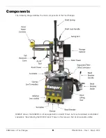

R980 Series of Tire Changers
20
P/N 5900158 — Rev. F - March 2022
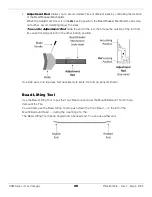
Prepare the Lube Bucket
The Tire Changer comes with a Lube Bucket (to hold your Lube) and a Lube Brush (to apply your Tire
Lube).
BendPak Ranger does not include any Tire Lube with the Tire Changer, as there are many options
available.
⚠
CAUTION
Only use Tire Lube that is approved by the Tire manufacturer for the Tire you are
changing. Using non-approved Lube could corrode the Wheel or cause Tire/Wheel
slippage and vibration issues.
Be sure to use enough lubricant without using too much. The point of lubricant is to
temporarily
reduce the friction between the Tire Bead area and the Rim. What you are looking for is a lubricant that
is slippery when wet but not slippery once dried. If you notice excessive amounts of lubricant on the
Tire or Rim, remove the excess.
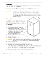
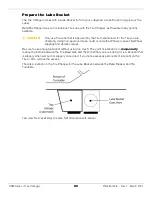
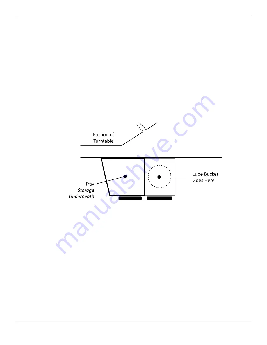
There is a location on the Tire Changer for the Lube Bucket: between the Bead Breaker and the
Turntable.
Top view. Not necessarily to scale. Not all components shown.
Summary of Contents for R980AT
Page 60: ...R980 Series of Tire Changers 60 P N 5900158 Rev F March 2022 Labels ...
Page 61: ...R980 Series of Tire Changers 61 P N 5900158 Rev F March 2022 ...
Page 62: ...R980 Series of Tire Changers 62 P N 5900158 Rev F March 2022 ...
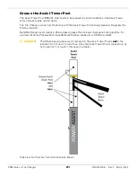
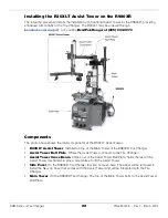
Page 83: ...R980 Series of Tire Changers 83 P N 5900158 Rev F March 2022 Assist Tower Optional ...
Page 87: ...R980 Series of Tire Changers 87 P N 5900158 Rev F March 2022 Maintenance Log ...


