background image


RML-1500XL ATV / Motorcycle Lift 

24


P/N 5900183 — Rev. E2 — May 2022 


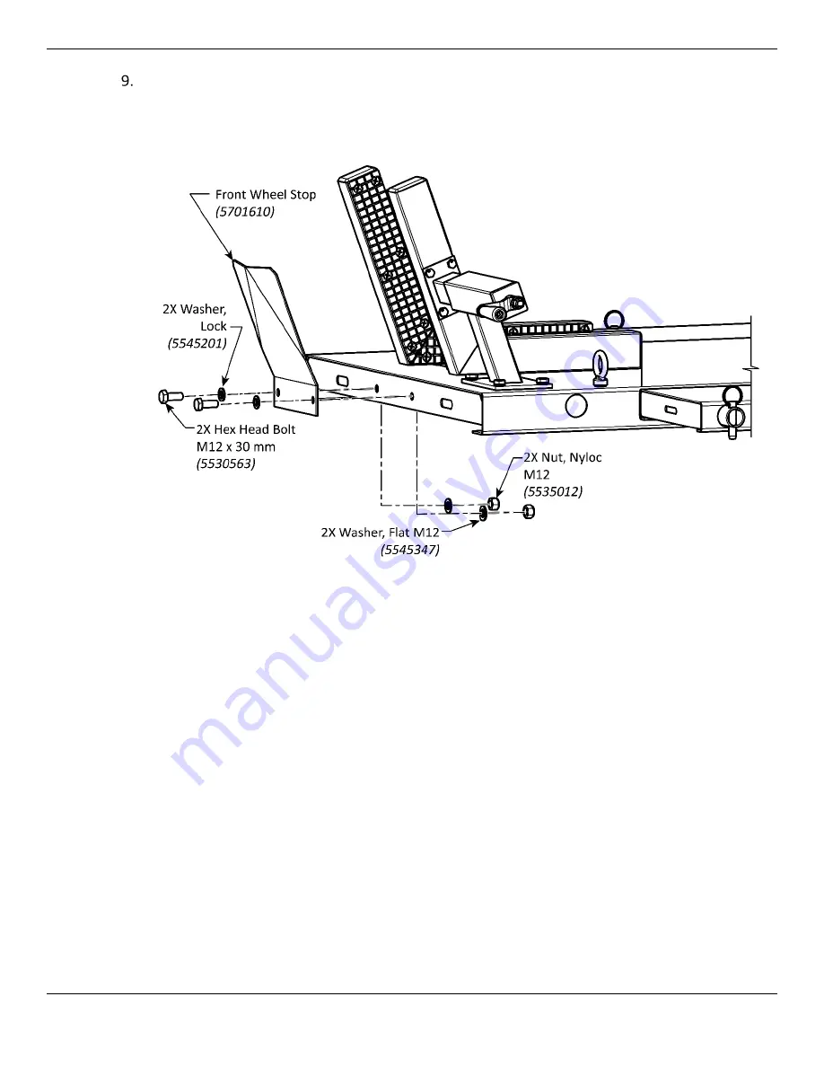
Retrieve the Front Wheel Stop and use two M12 Bolts (5530563), M12 Lock Washers 

(5545201), M12 Flat Washers (5545347), and M12 Nyloc Nut (5535012) sets to secure it to the 

end of the Top Deck. Refer to the figure below. 


Summary of Contents for RML-1500XL

Page 1: ...IMPORTANT SAFETY INSTRUCTIONS SAVE THESE INSTRUCTIONS Read this manual thoroughly before installing operating servicing or maintaining this Lift Failure to follow the instructions and safety precautions in this manual can result in serious injury or death Make sure all other operators also read this manual Keep the manual near the product for future reference By proceeding with installation and op...

Page 2: ...ur new product For full warranty details contact your nearest BendPak Ranger dealer or visit bendpak com support warranty Safety Your product was designed and manufactured with safety in mind However your safety also depends on proper training and mindful operation Do not install operate maintain or repair the unit without reading and understanding this manual and the labels on it Do not use this ...

Page 3: ...ul when installing operating maintaining or repairing this equipment failure to do so could result in property damage product damage injury or in very rare cases death Make sure only authorized personnel operate this equipment All repairs must be performed by an authorized technician Do not make modifications to the unit this voids the warranty and increases the chances of injury or property damag...

Page 4: ...f the bill of lading freight bill invoice and photographs if available Our willingness to assist in helping you process your claim does not make us responsible for collection of claims or replacement of lost or damaged materials Safety Considerations Read this entire manual carefully before using your new product Do not install or operate the product until you are familiar with all operating instr...

Page 5: ...anty and increases the chances of injury or property damage Do not use the Lift while tired or under the influence of drugs alcohol or medication Consider the work environment Keep the work area clean Cluttered work areas invite injuries Keep areas well lit Always make sure the Lift is secured on Safety Locks before attempting to work on or near a Vehicle Make a thorough inspection of the product ...

Page 6: ...before using it Check for damaged worn or missing parts Do not use it if you find any of these issues Take it out of service then contact an authorized repair facility your dealer or BendPak at 877 432 6627 or support BendPak com Symbols Following are the symbols used in this manual DANGER Calls attention to an immediate hazard that will result in injury or death WARNING Calls attention to a hazar...

Page 7: ...with the Side Extensions installed for lifting an ATV Top Deck Side Extensions Optional Makes the Top Deck wider Use for lifting an ATV Top Deck Front Extension Optional Makes the Top Deck longer Wheel Vise Opens and closes to let you securely hold the front tire of the Vehicle on the Top Deck Can be bolted to the Top Deck or to the Front Deck Extension Front Wheel Stop Prevents the Motorcycle Whe...

Page 8: ...y Locks Hydraulic Cylinder Raises and Lowers the Top Deck using hydraulic energy from the Air Hydraulic Pump Drive Up Ramps Two ramps wide enough when both are installed to accommodate ATVs Air Hydraulic Pump Uses pneumatic air power to provide hydraulic power to raise the Lift If you have a pressurized air supply available 40 to 120 psi at 105 in3 you can connect it to the Pump to raise the Lift ...

Page 9: ...se the Lift inside If you have to use it outside we recommend storing it inside moving it outside while you are using it then moving it back inside when not in use Keep the Lift clean and dry as much as possible especially the Air Hydraulic Pump Remove snow and ice promptly Top Deck extensions and Drive up Ramps may be slippery when wet or icy Q Can I put the Air Hydraulic Pump on either side of t...

Page 10: ...RML 1500XL ATV Motorcycle Lift 10 P N 5900183 Rev E2 May 2022 Specifications ...

Page 11: ...s 53 3 in 1 354 mm D Overall Width No Side Extension Decks 31 9 in 810 mm E Lowered Height 7 5 in 188 mm F Full Rise Top Deck 45 3 in 1 153 mm G Top of Stand Poles at Full Rise 108 in 2 740 mm Top Deck 1st Lock Position 24 5 in 625 mm Top Deck 6th Lock Position 40 3 in 1 023 5 mm Lifting Capacity 1 500 lbs 680 kg Air Supply 40 to 120 psi at 98 to105 in3 Power Supply Pump Compressed Air Hydraulic S...

Page 12: ... recommends having two or more persons work together to install the Lift Get the Right Tools You may need some or all of the following tools and supplies Metric Wrench Set Forklift or Shop Crane with Lifting Strap Metric Socket and Ratchet Set White Lithium Grease Metric Hex Key Set Pneumatic fittings and hose to connect to shop compressed air supply Finding a Location Keep the following in mind w...

Page 13: ...May 2022 Clearances The drawing below shows the amount of space around the Lift to operate it effectively WARNING For safety purposes only the operator should be within 30 feet 10 meters of the Lift during use Do not scale figure Not all components shown ...

Page 14: ... box remove that from its box as well Remove all of the components except the Base Top Deck Remove the bubble wrap from around those components that are wrapped lay them out near where you are going to set up the Lift Locate the plastic bag that holds the Nuts Bolts Washers and the other items you are going to need during installation BendPak Ranger recommends carefully laying them out near where ...

Page 15: ... is normal operation it also gives you a clear indication that the Top Deck is rising normally and lets you know when a Safety Lock has been passed Put a Lifting Strap around the middle of the Top Deck then use a Forklift or Shop Crane or other appropriate lifting device to raise the Lift up and then move it away from away from the Shipping Box or remove the shipping box WARNING Only allow trained...

Page 16: ...Deck Refer to the figure below Note If you want you use the Lift configured for Motorcycle service you will still require the two Drive Up Ramps to be installed If you are configuring for Motorcycle service do not install the Side Extensions or the Front Extension You will also not need to use the Extension Tubes If you are configuring the Lift for Motorcycle service you will have components left ...

Page 17: ... as you can when in the Motorcycle configuration To install the Lift in ATV Mode add the Extension Tubes Side Extensions and Ring Pins on both sides of the Top Deck the Front Extension over the front of the Top Deck and the two Ramps Refer to the figure below The procedures in this Manual assume you are installing the Lift in an ATV configuration If you are installing the Lift for Motorcycle servi...

Page 18: ...22 Putting the Lift Components into Place The following procedure assumes you have unpacked the Lift components and decided on a configuration to use Begin by arranging the components roughly as shown below The Wheel Vise Assembly is covered in the next section ...

Page 19: ...of the Ramps You can easily identify this end of the Lift because it has the drilled holes used later to install the Wheel Vise Assembly Align the holes in the side of the Front Extension with the holes in the side of the Top Deck Locate the three Top Deck Extension Tubes Push Two Extension Tubes through the holes in the sides of the Front Extension and Top Deck Refer to the figure below Do not sc...

Page 20: ...Extension Tubes Place one Extension on at a time one Side Extension on each side of the Top Deck Do not knock the Side Extension Tubes out when you put on the Side Extensions Locate the six Ring Pins 5505065 These should be located in the Parts Bag that came with the Lift Put the Ring Pins through the holes in both ends of the three Connecting Rods ...

Page 21: ...4 Thread one Drive Up Ramp Tube into the bottom of each Drive Up Ramp hand tight in the outside position on each Ramp Place the Drive Up Ramps on the Ramp end of the Lift Orient and verify the Drive Up Ramps are securely engaged in the guide holes in the Lift s Base Refer to the figure below Test each Drive Up Ramp to verify is stable ...

Page 22: ...Clamp Assembly Left Clamp and the Fixed Right Clamp Retrieve the 10 M10 Bolts 5530788 Flat Washers 5535013 Split Lock Washers 5545201 and M10 Nuts 5535013 These Bolts Washers and Nuts are located in the Parts Bag that came with the Lift Orient the Base Clamp Assembly so that the four holes in the base are aligned over the four holes in the Top Deck Use four of the Bolt Washer and Nut sets to secur...

Page 23: ...L 1500XL ATV Motorcycle Lift 23 P N 5900183 Rev E2 May 2022 Use six Bolt Washer and Nut sets to secure the Right Clamp to the Top Deck Refer to the figure below Do not scale Components removed for clarity ...

Page 24: ... P N 5900183 Rev E2 May 2022 Retrieve the Front Wheel Stop and use two M12 Bolts 5530563 M12 Lock Washers 5545201 M12 Flat Washers 5545347 and M12 Nyloc Nut 5535012 sets to secure it to the end of the Top Deck Refer to the figure below ...

Page 25: ...ake sure to implement them once the Lift is connected to an air supply Never exceed air line pressure ratings The Pump is a tripping hazard if you keep it on the ground Make sure everyone who uses the Lift or works near it is aware of the location of the Pump Only allow trained supervised personnel to operate the Lift Do not allow children or untrained personnel to operate the Lift Do not let anyo...

Page 26: ...ease Handle both have detents that mark and lock their position The Release Handle in the UP position puts the Lift s Safety Lock in the Off position The Lift will not engage any Safety Locks and may be lowered to the ground Refer to the figure below The Release Handle in the Down position puts the Lift s Safety Locks in the On position The Lift will engage the nearest Safety Lock only when loweri...

Page 27: ...the Top Deck and the Vehicle You will hear the Safety Lock Plate clank as it passes each Safety Lock Ladder Position Go just past the desired height then stop raising the Top Deck by releasing the PUMP Pedal Verify the Safety Release Handle is in the DOWN position to enable the Lift to engage the closest Safety Lock Ladder Position Press the RELEASE Pedal to back the Top Deck down onto the most re...

Page 28: ...e PUMP Pedal to raise the Top Deck and the Safety Lock Plate off of the Safety Lock it was engaged on Do not go past the next Safety Lock In order for the Lift to lower the Safety Lock Plate must not be engaged on a Safety Lock To do this you first have to move the Safety Lock Plate up off the Safety Lock it was engaged on Move the Safety Lock Release Handle up to the Release position until it sto...

Page 29: ...rs engage When all four Casters are engaged carefully roll the Lift to the desired location When the Lift is at the desired location turn each of the four Caster Adjustment Rods counterclockwise to lower the Base back down onto the ground WARNING Verify the Lift Casters are retracted and the Lift cannot move on its Casters before raising a Vehicle at the new location Lifting a Vehicle while the Li...

Page 30: ...rcycles To use the Stand Poles simply insert the Poles into the two openings at the rear of the Lift near the Movable Deck Plate Refer to the Figure below Lubrication Light lubrication on a monthly basis or on an as required basis with frequent use is recommended Use a White Lithium Grease on the Frame in the areas where the Scissor Rollers travel and on the Scissor Hinge points Refer to the figur...

Page 31: ...rts with original BendPak or BendPak approved parts or with parts that meet or exceed the original specifications To maintain your Lift WARNING Disconnect the Lift from its pressurized Air Supply before performing any troubleshooting procedures The Lift uses pneumatic air energy if your organization has Lockout Tagout policies make sure to implement them once the Lift is connected to a pressurized...

Page 32: ...ks and replace or repair faulty component Lift is making odd noises as it raises and lowers Verify the Lift is not overloaded Lubricate hinge points and the Frame where the Scissor Rollers travel using white lithium grease Lift wobbles as it raises or lowers Make sure the Vehicle on the Lift is correctly secured Lift becomes inoperative with Vehicle raised on the Lift If the Lift is engaged on a S...

Page 33: ...RML 1500XL ATV Motorcycle Lift 33 P N 5900183 Rev E2 May 2022 Labels ...

Page 34: ...RML 1500XL ATV Motorcycle Lift 34 P N 5900183 Rev E2 May 2022 Parts Drawings ...

Page 35: ...RML 1500XL ATV Motorcycle Lift 35 P N 5900183 Rev E2 May 2022 ...

Page 36: ...RML 1500XL ATV Motorcycle Lift 36 P N 5900183 Rev E2 May 2022 ...

Page 37: ...RML 1500XL ATV Motorcycle Lift 37 P N 5900183 Rev E2 May 2022 ...

Page 38: ...RML 1500XL ATV Motorcycle Lift 38 P N 5900183 Rev E2 May 2022 ...

Page 39: ...RML 1500XL ATV Motorcycle Lift 39 P N 5900183 Rev E2 May 2022 ...

Page 40: ...RML 1500XL ATV Motorcycle Lift 40 P N 5900183 Rev E2 May 2022 ...

Page 41: ...RML 1500XL ATV Motorcycle Lift 41 P N 5900183 Rev E2 May 2022 ...

Page 42: ...RML 1500XL ATV Motorcycle Lift 42 P N 5900183 Rev E2 May 2022 ...

Page 43: ...RML 1500XL ATV Motorcycle Lift 43 P N 5900183 Rev E2 May 2022 ...

Page 44: ...RML 1500XL ATV Motorcycle Lift 44 P N 5900183 Rev E2 May 2022 Maintenance Log ...

Page 45: ...RML 1500XL ATV Motorcycle Lift 45 P N 5900183 Rev E1 May 2022 Maintenance Log ...

Page 46: ...RML 1500XL ATV Motorcycle Lift 46 P N 5900183 Rev E1 May 2022 Maintenance Log ...

Page 47: ...RML 1500XL ATV Motorcycle Lift 47 P N 5900183 Rev E1 May 2022 Maintenance Log ...

Page 48: ...1645 Lemonwood Drive Santa Paula CA 93060 USA 2022 BendPak Inc All rights reserved rangerproducts com ...

Reviews: