background image


RML-600XL ATV / Motorcycle Lift 

21


P/N 5900381 — Rev. D — June 2019 

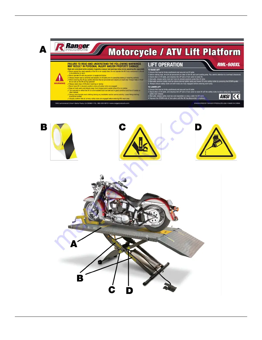
Labels 


Summary of Contents for RML-600XL

Page 1: ...by BendPak Inc in Southern California USA Made in China DANGER Read the entire contents of this manual before using this product Failure to follow the instructions and safety precautions in this manual can result in serious injury or death Make sure all other operators also read this manual Keep the manual near the product for future reference By proceeding with installation and operation you agre...

Page 2: ...value of your new product For full warranty details contact your nearest BendPak Ranger dealer or visit bendpak com support warranty Go to bendpak com support register your product and fill out the online form to register your product be sure to click Submit Safety Your new product was designed and manufactured with safety in mind Your safety also depends on proper training and thoughtful operatio...

Page 3: ...ins or repairs it DANGER Be very careful when setting up operating maintaining or repairing this equipment failure to do so could result in property damage product damage injury or in very rare cases death Make sure only authorized personnel operate this equipment All repairs must be performed by an authorized technician Do not make modifications to the unit this voids the warranty and increases t...

Page 4: ... in helping you process your claim does not make us responsible for collection of claims or replacement of lost or damaged materials Safety Considerations Read this manual carefully before using your new product Do not install or operate the product until you are familiar with all operating instructions and warnings Do not allow anyone else to operate the product until they are also familiar with ...

Page 5: ...ur distributor or BendPak Ranger at 805 933 9970 BendPak Ranger recommends making a thorough inspection of the product at least once a year Replace any damaged or severely worn parts decals or warning labels Symbols Following are the symbols used in this manual DANGER Calls attention to a hazard that will result in death or injury WARNING Calls attention to a hazard or unsafe practice that could r...

Page 6: ...05 mm wide Overall Width with Side Extensions 48 5 1 235 mm Main Ramp 21 5 550 mm long by 24 610 mm wide Side Ramps 21 5 550 mm long by 12 305 mm wide Lowered Height 8 203 mm Platform Height Top Safety Lock 32 812 mm Air Supply 90 to 100 psi Important Do not exceed 100 psi Use a pressure regulator to make sure the pressure to the Lift does not exceed 100 psi Additionally a water separator must be ...

Page 7: ...e Platform Has a red ball on its end making it easy to see Safety Locks Hold the Lift in position at the desired height once engaged The five Safety Locks are on the Scissor Arms Safety Lock Latch Located on the underside of the Platform it holds the Safety Lock Release Handle up and out of the way as you lower the Platform Ramps One Main Ramp for the Platform Two Side Extension Ramps one for each...

Page 8: ...hes to the incoming Air Supply An Air In Connector is supplied if you require a different sized connector replace the supplied connector with the desired connector Keep the Air Pump as far away from the Lift as possible it is a tripping hazard and you also do not want to step on and activate it by accident Top view on left side view on right Not necessarily to scale Not all components shown Platfo...

Page 9: ... parts of installing the Lift are difficult BendPak Ranger strongly recommends having at least three people work together to install the Lift Get the Right Tools You may need some or all of the following Wrench Set Socket and Ratchet Set Hex Key Set Forklift or Shop Crane Finding a Location Keep the following in mind when deciding on a location Air Supply You need an Air Supply 90 to 100 psi to ra...

Page 10: ...0381 Rev D June 2019 Clearances You need a certain amount of space around the Lift to use it effectively WARNING For safety only the Technician should be within 30 feet of the Lift during use Not necessarily to scale Not all components shown ...

Page 11: ...so that they are easily accessible when needed Keep the containers away from the area where you are setting up the Lift They are a tripping hazards while you are installing the Lift Platform Setup The first step in the installation process is to raise the Platform and engage it on a Safety Lock this makes all of the other installation tasks easier to do This procedure also sets up the Air Pump and...

Page 12: ...e sure to the Air In Connector on the Air Pump If the supplied Air In Connector is not appropriate for your setup you can replace it with a connector appropriate for your Air Supply system 7 Put the Long Rod through the square piece below the Ramp end of the Lift then thread a roller onto each end 8 Take the Platform off the lifting device 9 Use the Lower End of the Air Pump to lower the Platform ...

Page 13: ...all the Platform Extension but not the Side Extensions and their Connecting Poles then the Platform Extension is held in place by the Bolts and Nuts that also hold the Clamp in place Side Extensions 2 For wider Vehicles make the Lift wider but not longer The Side Extensions are held in place by two Connecting Poles and their Lock Bolts and Cotter Pins You can install use the Platform Extension and...

Page 14: ...sponding holes on their Platform 3 Slide the Platform Extension over the Main Platform on the Clamp end of the Main Platform The Platform Extension has holes for the Clamp just as the Main Platform does 4 Slide the two Connecting Rods into place through the Main Platform on each end The ends of the Connecting Rods are going to stick out through the Main Platform until you put the Side Extensions i...

Page 15: ...s Washers and Nuts are in the Parts Bag that came with the Lift 2 Orient the Handle Assembly so that the four holes in the base are aligned over the four holes in the Platform see the drawing above 3 Use four of the Bolt Washer and Nut sets to secure the Handle Assembly to the Platform BendPak Ranger recommends orienting your Bolts Washers and Nuts as shown here 4 Use four more Bolt Washers and Nu...

Page 16: ...ake sure everyone who uses the Lift or works near it is aware of the location of the Air Pump Avoid off center loads If the Lift seems to be having difficulty raising a Vehicle or the load appears unbalanced stop operation immediately carefully lower the Lift back down to the ground check everything out make any necessary adjustments then try again Do not stand on the Platform or let anyone else d...

Page 17: ... to secure the front wheel 7 Use additional restraints to secure the Vehicle on the Platform as needed 8 Check above and around the Vehicle on the Platform to make sure there is enough room to safely raise the Vehicle Only the technician should be within 30 feet while the Lift is in use WARNING Do not raise a Vehicle until you are sure all components are in place and working normally If you raise ...

Page 18: ...atform Only the Technician should be within 30 feet of the Lift while it is being used 2 Use the Raise End of the Air Pump to raise the Safety Lock Release Handle off the Safety Lock it was engaged on Do not raise the Safety Lock Release Handle past the next Safety Lock 3 Engage the Safety Lock Release Handle on the Latch on the underside of the Platform This keeps the Safety Lock Release Handle u...

Page 19: ...nstall it 3 Make sure there are no Vehicles on the Lift If there is emove it before moving the Lift 4 Remove the Main Ramp 5 Find the Dolly then attach the hole at the end of the Dolly to the Dolly Hook 6 Push down on the Dolly handle to raise the Lift a little then move it to the desired location The new location needs to meet the location requirements in Finding a Location and Clearances 7 Take ...

Page 20: ...orm lowering on its own Make sure the Platform is engaged on Safety Locks Lift is making odd noises as it raises and lowers Make sure the Lift is not overloaded Lubricate hinge points using white lithium grease Zerk grease fittings are located at lubrication points on the Lift Lift wobbles as it raises or lowers Make sure the Vehicle on the Lift is secure and balanced Lift becomes inoperative with...

Page 21: ...RML 600XL ATV Motorcycle Lift 21 P N 5900381 Rev D June 2019 Labels ...

Page 22: ...RML 600XL ATV Motorcycle Lift 22 P N 5900381 Rev D June 2019 Parts Diagrams ...

Page 23: ...Washer 6 56 Cam bearing spacer 2 17 Lock nut M16 4 57 Roller 2 18 Lifting arm 1 58 Mobile car 1 19 Bolt M16 80 2 59 Lube mouth 4 20 Bolt M12 25 1 60 R pin 2 21 Press ring 1 61 Revolver 1 22 Retaining ring 4 62 Joint 1 23 O Ring 1 63 Nut 4 24 Lifting arm 1 64 Frame Cylinder pivot shaft 1 25 Cylinder end plate 1 65 Front extension 1 26 Lock nut M10 12 66 Left side extension 1 27 Nut M10 16 67 Right ...

Page 24: ...1645 Lemonwood Drive Santa Paula CA 93060 USA 2019 BendPak Inc All rights reserved bendpak com ...

Reviews: