background image


21 of 48


20180521-Ver1


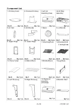
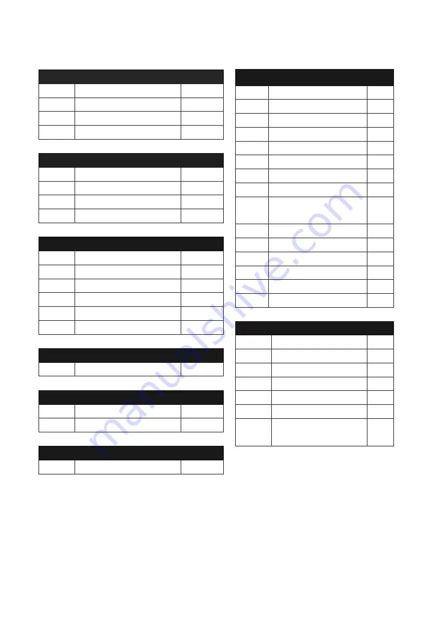
Box A 

Part 17 

Left Pivot Leg 

1pc 

Part 18 

Right Pivot Leg 

1pc 

Part 33 

Left Wheel Leg 

1pc 

Part 34 

Right Wheel Leg 

1pc 


Box B 

Part 12 

Charcoal Grill Cooking Grate 

2pcs 

Part 13 

Flame Tamer 

3pcs 

Part 23 

Side Burner Cooking Grate 

1pc 

Part 32 

Gas Grill Cooking Grate 

2pcs 


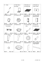
Box C 

Part 2 

Charcoal Chimney   

1pc 

Part 6 

Grill Handle   

1pc 

Part 8 

Lid Handle   

3pcs 

Part 16 

Leg Brace   

2pcs 

Part 30 

Grease Cup 

1pc 

Part 35 

Wheel   

2pcs 


Box E 

Part 22 

Side Burner Assembly   

1pc 


Box F 

Part 14   

Bottom Rack 

1pc 

Part 39 

Middle Panel   

1pc   


Box G 

Part 24 

Side Burner Control Panel 

1pc   


Box D 

Part 1 

Chimney Cover 

1pc 

Part 5 

Air Vent   

1pc 

Part 7 

Bezel   

6pcs 

Part 21 

Crank 

1pc 

Part 25 

Bottle Opener 

1pc 

Part 26 

Control Knob 

4pcs 

Part 27 

Side Burner Bracket (Left) 

1pc 

Part 28 

Side Burner Bracket (Right) 

1pc 

Part 29 

Charcoal Grease Tray 

Handle 

1pc 

Part 31 

Cooking Grate Lifter 

1pc 

Part 36 

Wheel Axle   

2pcs 

Part 37 

Wheel Cover 

2pcs 

Part 40 

Side Burner Supporting Bar 

1pc 

Part 9 

Upper Hinge 

4pcs 

Part 10 

Lower Hinge 

4pcs 


Not Place In Small Box 

Part 11 

Warming Rack 

2pcs 

Part 15 

Middle Brace   

2pcs 

Part 20 

Bottom Shelf   

1pc 

Part 38 

Tank Fixture   

1pc 

Part 4 

Grill Body Assembly 

1pc 

Part 3 

Left Lid Assembly (Gas) 

1pc 

Part 19 

Right Lid Assembly 

(Charcoal) 

1pc 


Summary of Contents for GR2071013-MM-00

Page 1: ...en using the appliance Keep this manual for further reference ATTENTION Please do not withdraw all parts from the packing boxes immediately Each assembly step in this instruction manual has instructed...

Page 2: ...linder under or near this appliance b Never fill the cylinder beyond 80 percent full and c If the information in a and b is not followed exactly a fire causing death or serious injury may occur PROP 6...

Page 3: ...air DO NOT leave the grill unattended while in use DO NOT use while under the influence of drugs or alcohol Keep the fuel supply hose away from heated surfaces DO NOT put grill in storage or move it...

Page 4: ...ight 18 inches 45 7 cm Diameter 12 inches 30 5cm and bottom ring diameter 8 inches 20 3 cm LP tank valve must have Type 1 outlet compatible with regulator or appliance Safety relief valve UL listed Ov...

Page 5: ...OT insert any foreign objects into the valve outlet Damage to the back check could result A damaged back check can cause a leak possibly resulting in explosions fire severe bodily harm or death Place...

Page 6: ...ebris Remove any debris Inspect hose for damage Never attempt to use damaged or obstructed equipment See local L P gas dealer for repair 5 When connecting regulator assembly to the valve hand tighten...

Page 7: ...ure of 50 water and 50 liquid dishwashing soap 2 Open the lid 3 Ensure all control knobs are set to the OFF position 4 Turn on the fuel supply at the cylinder valve Turn the cylinder valve knob one tu...

Page 8: ...body as far away from the burner as possible while lighting LIGHTING THE MAIN BURNER OF GRILL 1 Read all instructions before lighting 2 Open lid during lighting 3 Light the IGNITION BURNER first Push...

Page 9: ...TCH LIGHTING THE MAIN BURNERS 1 Turn OFF all burner valves 2 Make sure the lid is open 3 Place a lighted match between the coils on the extension rod and hold next to the burner 4 Turn the control kno...

Page 10: ...ed burner flipping it every 30 seconds to one minute until it s done The whole process will not take over 4 to 5 minutes to cook Or you can move the seared meat to the non infrared side of the grill a...

Page 11: ...obstruction which could result in a fire in and around burner tubes This type of fire is known as flashback and can cause serious damage to your grill and create an unsafe operating condition for the...

Page 12: ...ner may cause explosion and or fire resulting in serious bodily injury and or property damage When an appliance is supplied on casters and is connected to the supply piping by means of a connector for...

Page 13: ...mmended to clean cooking surfaces while grill is hot CHARCOAL GRILL GENERAL WARNINGS WARNING The maximum weight of charcoal to be used is 3 3lb 1 5kg Too much charcoal may cause the gas component to o...

Page 14: ...grill unattended when in use When adding charcoal and or wood use extreme caution and follow instruction in Adding Charcoal Wood during cooking section of this manual Do not store or use grill near g...

Page 15: ...of your grill make sure that hot coals and wood do not touch the walls of grill IF USING CHARCOAL CHIMNEY STARTER PROCEED TO STEP 5 If you choose to use charcoal lighting fluid ONLY use charcoal light...

Page 16: ...ive rust the unit must be cured periodically and covered at all times when not in use OPERATING INSTRUCTIONS WARNING DO NOT use grill without charcoal ash tray in place DO NOT attempt to remove charco...

Page 17: ...id is opened Step 4 Place cooking grates on grill support lips Use charcoal tray handle adjuster to position charcoal grates to desired cooking level WARNING Always wear oven mitts gloves when adjusti...

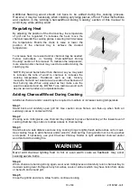
Page 18: ...en using wood as fuel make sure the wood is seasoned and dry DO NOT use resinous wood such as pine as it will produce an unpleasant taste Adding Charcoal Wood During Cooking Additional charcoal and or...

Page 19: ...f rust appears on the exterior surface of your grill clean and buff the affected area with steel wool or fine grit emery cloth Touch up with a good quality high temperature resistant paint Never apply...

Page 20: ...all small parts from the packing boxes immediately Each assembly step in this instruction manual has instructed you to find the particular part s from the packing box quickly We strongly recommend tha...

Page 21: ...ddle Panel 1pc Box G Part 24 Side Burner Control Panel 1pc Box D Part 1 Chimney Cover 1pc Part 5 Air Vent 1pc Part 7 Bezel 6pcs Part 21 Crank 1pc Part 25 Bottle Opener 1pc Part 26 Control Knob 4pcs Pa...

Page 22: ...22 of 48 20180521 Ver1 Product Diagram...

Page 23: ...Box C Qty 1 pc Box D Qty 6 pcs Box C Qty 3 pcs 9 Upper Hinge 10 Lower Hinge 11 Warming Rack 12 Charcoal Grill Cooking Grate Box D Qty 4 pcs Box D Qty 4 pcs Qty 2 pcs Box B Qty 2 pcs 13 Flame Tamer 14...

Page 24: ...D Qty 1 pc Box D Qty 4 pcs Box D Qty 1 pc Box D Qty 1 pc 29 Charcoal Grease Tray Handle 30 Grease Cup 31 Cooking Grate Lifter 32 Gas Grill Cooking Grate Box D Qty 1 pc Box C Qty 1 pc Box D Qty 1 pc Bo...

Page 25: ...ware List Item No Item name Diagram Qty A M6 X 12mm Bolt Black 39 B M12 Washer 2 C Plastic Rivet 3 D M6 X 15mm Bolt Black 8 E Hex Nut Wrench 1 F M6 X 25mm Bolt Black 4 G Cotter Pin 9 H M6 Locking Nut...

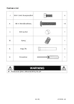
Page 26: ...6 of 48 20180521 Ver1 Hardware List J M6 X 12mm Hexagonal Bolt 4 K M6 X 35mm Bolt Black 16 L M8 Cap Nut 1 M Spring 1 N Hinge Pin 4 O Screwdriver 1 WARNING Please wear gloves while assembling the grill...

Page 27: ...27 of 48 20180521 Ver1 Replacement Part List I...

Page 28: ...ht 4d Charcoal Tray 14 Bottom Rack 29 Charcoal Grease Tray Handle 4e Charcoal Tray Lifter 15 Middle Brace 30 Grease Cup 4f Charcoal Tray Lifter Bar 16 Leg Brace 31 Cooking Grate Lifter 4g Crank Holder...

Page 29: ...ght Wheel Leg 34 by using 4 pcs of Bolts A Tips Each Wheel Leg has a hole at the bottom Please see the Gray Triangles Step 2 Attach the Leg Brace 16 to the Left Pivot Leg 17 and Right Pivot Leg 18 by...

Page 30: ...Tips Make sure the middle bracket must be on top during the assembly and pointing into inside Please see the Gray Triangles Step 4 Attach the Bottom Shelf 20 to the Legs assembly by using 4 pcs of Bo...

Page 31: ...heel Axle 36 The Wheel Axle can be fastened the Hex Nut Wrench E Attach the Wheel Cover 37 to the wheels Step 6 Attach the Middle Panel 39 to the bottom cart by using 4pcs of Bolts A Tips Make sure th...

Page 32: ...the bottom cart by using 2 pcs of Bolt A Tip Attach the bottom rack to bracket first per a then fasten the bolts per b Please see the Gray Triangles Step 8 Attach the Tank Fixture 38 to the big hole o...

Page 33: ...cart braces then tighten all bolts If either of the middle brace cannot be aligned with the front or back grill body Simply adjust the position of middle panel and middle brace by loosening the top bo...

Page 34: ...k 21 into the crank holder on the charcoal side of grill body then using 1 pc of Cotter Pin G to fix the crank Step 12 Attach the Grill Handle 6 to the grill body by using 4 pcs of Hexagonal Bolt J Th...

Page 35: ...8 20180521 Ver1 Step13 Attach Left and Right Side Burner Bracket 27 and 28 to the grill body by using 2 pcs of Bolt A Step14 Attach the Side Burner Assembly 22 on the side burner brackets per followin...

Page 36: ...36 of 48 20180521 Ver1 Step15 Secure the side burner assembly by using 2pcs of Bolt A Step16 Attach the Bottle Opener 25 to the Side Burner Control Panel 24 by using 2 pcs of Bolt I...

Page 37: ...out the side valve with gas regulator assembly from main control panel at grill side per following shown Understand the construction of side burner gas components it would help you proceed the side bu...

Page 38: ...NTION DO NOT OVER TWISTING THE FLEXIBLE STAINLESS STEEL GAS TUBE GENTLY bend the Flexible Stainless Steel Gas Tube its route is similar to illustration a Remove the pre assemble screws at Side Burner...

Page 39: ...39 of 48 20180521 Ver1 Step 19 Attach the Side Burner Gas Valve to Side Burner Control Panel by using the removed pre assemble screws per illustration a and b...

Page 40: ...trol Panel to the Control Panel Bracket Remember to check that the top lip of the side burner control panel should be hooked onto the side burner control panel brackets During putting the control pane...

Page 41: ...following points 1 Make sure the Gas Valve Nozzle has already engaged with the Side Burner Venturi You can see and check through the observation hole at side burner bracket Please see the Gray Triang...

Page 42: ...42 of 48 20180521 Ver1 Step 23 Attach the Control Knobs 26 to each gas valve Step 24 Attach the Lid Handle 8 and Bezel 7 to the side burner lid by using 2 pcs of Bolt D...

Page 43: ...eft Lid Assembly 3 by using 8 pcs of Bolt K respectively Tips Remember to check the shape of the hinges and make sure to use the correct hinges for this step Please see the grey triangles Step 26 Put...

Page 44: ...8pcs of Bolt K Tips Remember to check the shape of the hinges and make sure to use the correct hinges for this step Please see the grey triangles Step 28 Attach the Right and Left Lid on the grill bod...

Page 45: ...ng Grate 12 to the grill body The Cooking Grate Lifter 31 is for lifting up the cooking grates during the cooking Step 30 Attach the Warming Rack 11 to the grill chambers The top rods of warming rack...

Page 46: ...f 48 20180521 Ver1 Step31 Take out the grease tray from the grill body Attach Charcoal Grease Tray Handle 29 by using 2 pcs Bolt A Also put the Grease Cup 30 to the Grill body as shown Assemble Comple...

Page 47: ...ly connected to three quarters additional turn until solid stop Tighten by hand only do not use tools 3 Clear burner tubes Check for bent or kinked hose 4 Re engage burner and valve per assembly proce...

Page 48: ...ON Manufacturer s liability shall be limited to the delivery of a good merchantable Product and if necessary the repair or replacement at manufacturer s option of any defective part or unit 7 TRANSFER...

Reviews: