4 MAINTENANCE
GB-24
4.17 CARE AND CLEANING _____________________________________________________
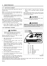
Wash the tractor and implements after each use. Keep the
equipment clean.
Note: Do not wash any portion of the equipment while it is
hot. Do not use high pressure spray or steam. Use cold
water and automotive cleaners.
1.
Use compressed air to clean engine and radiator fins. A
special blow gun is available through Textron Turf Care
And Specialty Products Dealer.
2.
Use only fresh water for cleaning your equipment.
Note: Use of salt water or affluent water has been known
to encourage rust and corrosion of metel parts resulting
in premature deterioration or failure. Damage of this
nature is not covered by the factory warranty.
3.
Do not spray water directly at the instrument panel,
ignition switch, controller or any other electrical
components, or at bearing housings and seals.
4.
Clean all plastic or rubber trim with a mild soap
solution or use commercially available vinyl/rubber
cleaners.
Repair damaged metal surfaces and use Textron Turf Care
And Specialty Products touch-up paint. Wax the equipment
for maximum paint protection.
4.18 ELECTRICAL SYSTEM _____________________________________________________
General precautions that can be taken to reduce
electrical problems are listed below.
1.
Make certain all terminals and connections are clean
and properly secured.
2.
Check the operator backup system, fuses and
circuit breakers regularly.
If the operator backup system does not function
properly and the problem cannot be corrected,
contact an authorized Textron Turf Care And
Specialty Products Dealer.
3.
Keep the wire harness and all individual wires away
from moving parts to prevent damage.
4.
Make sure the seat switch harness is connected to
the main wire harness.
5.
Check the battery and battery charging circuit.
6.
Do not wash or pressure spray around electrical
connections and components.
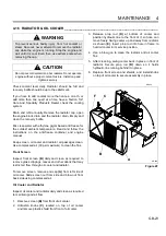
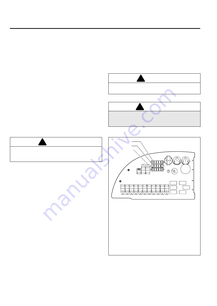
Circuits are protected by a circuit breaker (located above
batteries), plus fuses and relays mounted under the
instrument panel (See Figure 4G and Chart 4H).
Figure 4G
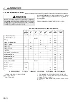
Chart 4H identifies the location and basic functions of the electrical relays located under the control panel. For more
detailed information refer to the electrical schematic in this manual.
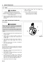
CAUTION
Clean grass and debris from cutting units, drives, muffler
and engine to prevent fires.
WARNING
NEVER use your hands to clean cutting units. Use a
brush to remove grass clippings from blades. Blades are
extremely sharp and can cause serious injuries.
!
!
CAUTION
Always turn the igniton switch off and remove the
negative battery cable (Black) before inspecting or
working on the electrical system.
!
F1 F2 F3 F4
F5 F6 F7 F8
F9F10F11F12
FUSES
F1
5A Spare
F2
5A
Spare
F3
15A Spare
F4 15A Spare
F5
5A
Ignition
F6
5A
Gauges
F7
5A
Fuel solenoid, Glow Plugs
F8
15A
Seat air system
F9
5A
Cruise Control
F10
5A
4-WD Solenoid
F11
15A
Deck Valve
F12
Not Used
HR006
Summary of Contents for HR 9016 Turbo
Page 31: ......
Page 161: ...SOLUZIONE DEI PROBLEMI 5 I 33...
Page 162: ......
Page 280: ......
Page 281: ......

