en-6
2 INTRODUCTION
B
A
C
FIG 2
FIG 1
2.6
ASSEMBLY __________________________________________________________
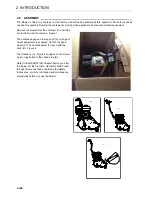
The Mower is fitted to a container at the factory and will need assembly before operation. Some tools will be
needed for assembly. Discard the container according to the applicable local environmental requirement.
Remove the mower from the container. The handles
are found around the chassis - Figure 1.
The handles engage on the lug shaft (A). A range of
height adjustment is available. Tighten the hand
wheel (C) The handles adjust for reach with the
bolts (B) - Figure 2.
The Grassbox (A) - Figure 3 engages on the mower
by two lugs bolted to the chassis lug (B).
Refer to the OPERATION Chapter before you start
the mower for the first time. Operators MUST read
through this manual and understand the Safety
Instructions, controls, lubrication and maintenance
procedures before any use the Mower.
FIG 3
B
Summary of Contents for Matador 71
Page 9: ...en 7 INTRODUCTION 2 NOTES...
Page 10: ...Parts 8 MATADOR Illustration Engine Group 4300619_Group_Engine_71cm...
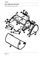
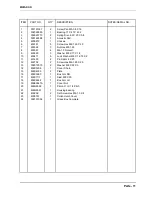
Page 12: ...MATADOR Illustration Parts 10 MAIN FRAME AND GRASS BOX 4299911_Main Frame and Grass Box...
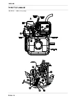
Page 14: ...Parts 12 MATADOR Illustration THROTTLE LINKAGE 4299991_Throttle_Linkage...
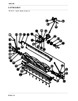
Page 16: ...Parts 14 MATADOR Illustration a b c CUTTING UNIT lmac067_Matador_Cutting_Unit...
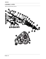
Page 18: ...Parts 16 MATADOR Illustration LANDROLL CLUTCH 302r0007_Matador_Drive eps...
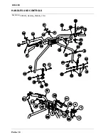
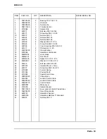
Page 20: ...Parts 18 MATADOR Illustration HANDLES AND CONTROLS 4299912_Handles_Matador_71cm...
Page 24: ...Parts 22 MATADOR Illustration FRONT ROLL 302r0005_Matador_Front_Roll eps...
Page 26: ...Parts 24 MATADOR Illustration LANDROLL 302r0006 2_Matador_Landroll eps...
Page 30: ...Parts 28 MATADOR Illustration MATADOR TOW BAR 71cm TRAILING SEAT LMAA628_Matador_Seat eps...
Page 32: ...Parts 30 MATADOR Illustration LANDROLL RUBBER COVERED 302R0006_rubber coated eps...


