background image


2. PRODUCT CHARACTERISTICS


>


rated voltage: 

230V~ / 50Hz


>


refrigerant: 

HFC-452A

; ODP = 0, GWP = 2140 

>


operating temperature: 

+2°C

 ÷ 

+10°C


>


sound pressure level: 

<70dB (A)


Device / module* 

width 

[mm]


Device 

depth 

[mm]


Usable depth of 

the device 

[mm]


Usable width / depth 

of shelves 

[mm] 

Usable exposition 

area 

[m

2

]


LED power 

[W]


1330 / 1250 

700 

435 

1220 / 342 

2,23 

20 

1960 / 1880 

930 / 342 

3,36 

25 

* - refers to module dimensions (without glass sides – sides additionally 75mm)


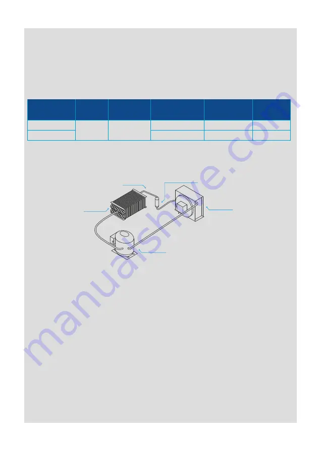
3. COOLING SYSTEM DIAGRAM 


4. WIRING SYSTEM 


1. The device is equipped with the protective PE cable.  
2. Before connecting the device to the power supply, check the compatibility of the mains 

voltage with the device supplying voltage (data on the plate).  

3. Connecting the device to the mains socket should be made so that the plug of the 

connecting cable is visible and easily accessible for the service. 

4. The device should be connected to a separate, properly made electrical circuit protected 

by a fuse no greater than 16 A with a B-characteristic, ended with a socket with a 
protective pin (for model RCh-SR / 125, 133 – not stronger than 10A) 

5. The device may be started only after confirming the effectiveness of the shock protection 

with the results of measurements carried out in accordance with the applicable 
regulations. 

6. Before carrying out any maintenance or cleaning, turn off the device with the switch and 

then remove the plug from the mains socket. 

7. The device is started after connecting the plug to the mains socket, and then by turning 

on the switch. The backlight of the switch indicates that the device has been turned on. 

8. Any repair of electrical installation and replacement of the connection cable (only into 

original one available from the manufacturer) may be carried out by an authorized 
electrician only.


evaporator 

capillary 

chemical filter-dryer 

condenser 

compressor 

Summary of Contents for RCh-O

Page 1: ...1 TRANSLATED FROM ORIGINAL USER MANUAL MODULAR MULTIDECK REFRIGERATED DISPLAY RCh O RCh SR 11 2021 EN...

Page 2: ...roduct characteristics 5 3 Cooling system diagram 5 4 Wiring system 5 5 Wiring system diagram 6 6 Drawings 7 7 Positioning start up and operation 9 8 Maintenance 10 9 Transport and equipment 11 10 Tem...

Page 3: ...ing of the device to the mains may result in an electric shock 2 In the event of sparks or breakdowns immediately disconnect the device from the power supply by pulling the plug from the socket and ca...

Page 4: ...l sliding doors 196 70 device dimensions see table in p 2 Important information on the rating label of each device In the case of contact with the service department prepare the following data for eff...

Page 5: ...for the service 4 The device should be connected to a separate properly made electrical circuit protected by a fuse no greater than 16 A with a B characteristic ended with a socket with a protective p...

Page 6: ...protection 4 starting relay 5 starting capacitor 6 run capacitor 7 compressor s electric node 8 condenser fan 9 case of evaporator fans 10 evaporator fans 11 main switch 12 lighting switch Fig 1 Elect...

Page 7: ...Lighting switch Electronic temperature controller Fig 4 Cross section RCh O sliding doors night blind shelf support air duct insulation bottom fan compressor LED lighting shelf shelf edge strip night...

Page 8: ...r the whole length 40 kg but maximum load of one hook 10 kg It is allowed to install only three crossbars one below the other It is possible to install crossbar closer to the back Only one crossbar is...

Page 9: ...before start up Place the device in the required location and make sure all the feet are fully screwed almost as far as they can go Then unscrew the feet and using a level adjust legs until the device...

Page 10: ...eral maintenance should be done by the user as follows 1 washing with water of the temperature not more than 40 C with addition of natural cleaning agents To wash and clean the device it is forbidden...

Page 11: ...mpressor s start up is delayed because of protective procedure It flashes in the cycle two flashes break when there is continuous operation mode activated 2 FAN The symbol is visible when there are ev...

Page 12: ...g power supply of the controller on will cause return to the parameters fabric settings there will be shown CF symbol on the display In the parameters setting mode its pressing changes the information...

Page 13: ...arameter setting increase or decrease setting value by means of the UP and DOWN switches press the SET switch to temporarily save the entered new value it will cause as well return to the parameters l...

Page 14: ...ended after exceeding the maximum duration rather than when reaching the end defrost set point The message disappears when the next defrost ends correctly EF displayed during operation or on power up...

Page 15: ...hamber loud operation of the aggregate characteristic clicking coming out of the aggregate chamber every few minutes Goods loaded in the device chamber should be initially cooled up to maximum 4 C abo...

Page 16: ...000009031 tel 48 81 742 53 10 do 14 e mail rapa rapa lublin pl Service tel 48 81 718 46 08 e mail service rapa pl www rapa pl en The package should be removed according to the regulations of environme...

Reviews: