background image

18 


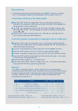
Description of the main signals and alarms 
 

LED flashing


The activation of the corresponding function is delayed by a timer 


awaiting an external signal or disabled by another procedure that is 

already in progress. e.g. if is a continuous cycle in progress and a defrost is called, 
the latter will remain pending until the end of the continuous cycle, and the 
corresponding LED (defrost) will flash. 


OFF flashing 

– state of the controller - OFF, to return to working mode (ON) 

press and hold ON/OFF button for more than 3 sec. 

E0 steady


– control probe error (1) – active sound signal: 


probe not working: the probe signal is interrupted or short-circuited; 


probe not compatible with the instrument. 

The E0 alarm signal is constant when it is the only active alarm (the temperature 
value is not displayed). 

E0 flashing


– control probe error (1) – the alarm signal E0 is steady if it is the only 

active alarm (the temperature value is not displayed), while it flashes if other alarms 
are active or the second probe is displayed.


E1 flashing


– evaporator probe error (2): 


probe not working, the probe signal is interrupted or short-circuited; 


probe not compatible with the instrument. 

Ed flashing


– The last defrost ended after exceeding the maximum duration rather 

than when reaching the end defrost set point. The message disappears when the 
next defrost ends correctly. 

EF displayed during operation or on power-up


– operating parameter reading 

error (controller automatic reset). Alarm reappearance after automatic reset 

– it is 

necessary to check the controller as there is no guarantee to keep the original 
precision of the operation. 

EE 

 data errors 

– In certain operating conditions, the instrument may detect errors 

in the data saved. These errors may compromise the correct operation of the 
instrument. If the microprocessor detects a data saving error, the display shows the 
message 

“EE”.

 If the fault persists, the controller needs to be replaced. If, on the 

other hand, the message disappears, it can continue to be used. When 

“EE” 

error 

occurs frequently and/or remains for some time, the controller should be checked, 
as the original precision may not be guaranteed.


LO flashing


 low temperature alarm. The probe has measured a temperature 

lower than the set point by a value that exceeds parameter AL: 


check parameters AL, Ad and A0. 

The alarm is automatically reset when the temperature returns within the set limits  
(see parameter AL). 

HI flashing


– high temperature alarm. The probe has measured a temperature 

higher than the set point by a value that exceeds parameter AH. 


check parameters AH, Ad and A0.


Summary of Contents for SiX Series

Page 1: ...1 TRANSLATED FROM ORIGINAL USER MANUAL MODULAR REFRIGERATED COUNTERS SiX line 03 2021 PL...

Page 2: ...Product characteristics 5 3 Cooling system diagram 5 4 Wiring system 5 5 Wiring system diagram 6 6 Drawings 7 7 Positioning start up and operation 9 8 Maintenance 9 9 Transport and equipment 10 10 Tem...

Page 3: ...shock 2 In the event of sparks or breakdowns immediately disconnect the device from the power supply by pulling the plug from the socket and calling an authorized service technician 3 It is necessary...

Page 4: ...S 197 120 L type of the device refrigerated counter S Si X Xi models 197 120 device dimensions see table p 2 Important information on the rating label of each device In the case of contact with the s...

Page 5: ...able is visible and easily accessible for the service 4 The device should be connected to a separate properly made electrical circuit protected by a fuse no greater than 10 A with a B characteristic e...

Page 6: ...6 5 WIRING SYSTEM DIAGRAM Modular refrigerated counter with two aggregates SPR2 G2 MS2 applicable to counters of the length of 197 cm...

Page 7: ...Keep the distance from the glass pane and side of the storage Pic 2 a Pic 2 b Cross section A A Pic 2 L S version temperature controller thermostat depth with open door depth aggregate switch light s...

Page 8: ...Cross section A A Pic 4 a Shows distribution of the goods in the exposition and the storage Pic 4 b Shows distribution of the goods along the length of the exposition and storage Keep the distance fr...

Page 9: ...ng putting on the vent Pic 5 a Removing the vent 1 Vent mounted correctly 2 Grab the vent with both hands and lift up 3 Then tilt the vent upwards slightly to yourself 4 Slide the vent from the bottom...

Page 10: ...ottom mounting bar 7 Then push the vent upwards slightly to yourself 8 Vent mounted correctly shown places for hooking the vent CAUTION Important while putting on In the counter of the length of 197 c...

Page 11: ...air guide in the L X and L Xi counters Glass air guides in the L X and L Xi counters have cut corners Slide the glass air guides gently into the gap with the cut corners downwards glass air guide cut...

Page 12: ...way of basing the night covers on the guides L X counter insert night cover with cut corners upwards insert night covers with grips on the outside of the device night covers moving on each other nigh...

Page 13: ...Below there is shown the way of basing the night covers on the guides L S counter insert night cover with grips on the outside of the device night covers moving on each other night cover guide on the...

Page 14: ...he load has to be distributed evenly on the whole Surface of the top Front glass panes has to be closed carefully in the final closing phase holding them in place of the holders indentations in the gl...

Page 15: ...when the compressor operates It flashes when the compressor s start up is delayed because of protective procedure It flashes in the cycle two flashes break when there is continuous operation mode act...

Page 16: ...ng power supply of the controller on will cause return to the parameters fabric settings there will be shown CF symbol on the display In the parameters setting mode its pressing changes the informatio...

Page 17: ...parameter setting increase or decrease setting value by means of the UP and DOWN switches press the SET switch to temporarily save the entered new value it will cause as well return to the parameters...

Page 18: ...ended after exceeding the maximum duration rather than when reaching the end defrost set point The message disappears when the next defrost ends correctly EF displayed during operation or on power up...

Page 19: ...um cleaner equipped with brush gently along fins to not to bend the lamella Device loaded with warm products hot air coming out of the aggregate chamber loud operation of the aggregate characteristic...

Page 20: ...Ceramiczna Street BDO 000009031 tel 48 81 718 46 50 51 e mail rapa rapa lublin pl www rapa pl en The package should be removed according to the regulations of environmental protection The warranty ca...

Reviews: