14
4.3.12 SSI Clock Frequency (
TNSDCR
→
SSISPD
)
The TDD2 will output an SSI clock with a frequency of 178kHz by default. This speed is slow
enough to accommodate most cabling situations, but when using a very long cable it may be necessary to
use a slower SSI clock. The SSI clock speed can be reduced to 100kHz, 75kHz, 50kHz, or 40kHz.
4.4
Digital Output Settings (Optional)
The Digital Outputs menu item (
) will only appear if a 1- or 5-channel limit switch
daughter board is installed in the TDD2. When this menu appears, the digital outputs (limit switch outputs)
of the TDD2 can be configured to turn on and off based on the displayed position or one of the magnets in a
multi-magnet system. Each of the five outputs is configured independently. Each output has a low position
bound and a high position bound, which delineate the position range where the output is active. Each output
can be configured to be active when the selected position source is inside the bounds or when the selected
position source is outside the bounds.
A position is considered inside the position bounds when the position is equal to or greater than the
smaller position bound and less than or equal to the larger position bound. A position is considered to be
outside the bounds when the position is less than the smaller position bound or greater than the larger
position bound.
4.4.1
Digital Output Lower Bound (one per digital output)
Each digital output has a lower bound that defines one side of the range of positions where the
output will be active. The “Lower” bound is the smaller position of the two bounds. A position that is
greater than or equal to the lower bound and less than or equal to the upper bound will be considered inside
the position range for the digital output.
4.4.2
Digital Output Upper Bound (one per digital output)
Each digital output has an upper bound that defines one side of the range of positions where the
output will be active. The “Upper” bound is the larger position of the two bounds. A position that is less
than or equal to the upper bound and greater than or equal to the lower bound will be considered inside the
position range for the digital output.
4.4.3
Digital Output Position Source (one per digital output)
Each digital output has a position source setting that defines the source of the positions that will be
compared with the position bounds. The position source can either be the displayed position (however the
currently displayed position is determined), or the position from a particular magnet in a multiple-magnet
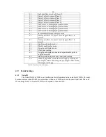
configuration. The position source setting can be set to an integer from 0 to 15. A value of 0 indicates that
this digital output will be based on the displayed position. A value of 1 to 15 causes the digital output to be
controlled by the position of magnet 1 to 15. All applicable offsets and scaling is performed for any position
used for the digital output calculations.
PS Value
Controlling position
0
Displayed position
1
Magnet 1
2
Magnet 2
3
Magnet 3
4
Magnet 4
5
Magnet 5
6
Magnet 6
7
Magnet 7
8
Magnet 8
9
Magnet 9
10
Magnet 10
11
Magnet 11
12
Magnet 12
13
Magnet 13


