UHA S
TANDARD
U
NIT
H
EATER
I
NSTALLATION
O
PERATION AND
S
ERVICE
M
ANUAL
16 of 59
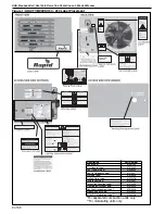
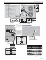
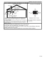
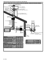
Figure 10: Concentric Vertical and Horizontal Vent Termination - Separated Combustion Heater
Vent**
Air Intake*
Concentric
Vent Box
Vertical
Option
10' (3 m)
Maximum
Horizontal
Option
Concentric
Vent Box
Combustion Air Terminal
Vent Terminal
with Baffle Plate
Flashing
(By Others)
4" (10 cm)
Type B-1Vent
Storm Collar (By Others)
(Attach with 3 sheet metal screws)
UHAS 150-250:
6" (15 cm) Diameter
Single Wall
UHAS 300-400:
8" (20 cm) Diameter
Single Wall
Vent**
6" (16 cm)
Minimum
12" (31 cm)
Maximum
6" (16 cm) Minimum
12" (31 cm) Maximum
Combustion
Air Terminal
Vent Terminal
with Baffle Plate
4"
(10 cm)
Type
B-1
Vent
Air Intake*
Storm Collar (By Others)
(Attach with 3
sheet metal screws)
12" (31 cm) Minimum from
roof to combustion air terminal
Flashing
(By Others)
12" (31 cm)
Minimum from
wall to combustion
air terminal
Description
Part Number
Qty.
Concentric Vent Kit (150 - 250)
UHVK1
Concentric Vent Box Top & Side Assembly
90504113
1
Concentric Vent Box Bottom Assembly
90504112
1
Screw #6 x 3/8 Self Drilling
91119100
14
4" Vent Terminal with Baffle Plate
90502102R
1
6" Combustion Air Terminal
90502103
1
Description
Part Number
Qty.
Concentric Vent Kit (300 - 400)
UHVK2
Concentric Vent Box Top & Side Assembly
90504013
1
Concentric Vent Box Bottom Assembly
90504012
1
Screw #6 x 3/8 Self Drilling
91119100
14
4" Vent Terminal with Baffle Plate
90502102R
1
8" Combustion Air Terminal
90502104
1
Model
**Vent Diameter
UHA[T][M][X]S 150 - 400
4" (10 cm)
Model
*Air Intake Diameter
UHA[T][M][X]S 150 - 250
4" (10 cm)
UHA[T][M][X]S 300 - 400
5" (13 cm)
Summary of Contents for UHAM 150
Page 2: ......
Page 4: ......
Page 8: ......
Page 50: ...UHA STANDARD UNIT HEATER INSTALLATION OPERATION AND SERVICE MANUAL 42 of 59 14 1 General ...
Page 65: ...SECTION 16 SPECIFICATIONS 57 of 59 16 4 Dimension Data for Models UHA T M X S 300 400 ...
Page 68: ......
Page 69: ......
Page 70: ......
Page 71: ......
Page 72: ......

