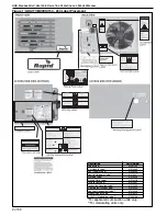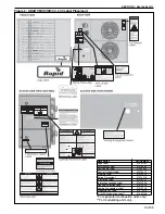
Figure 1: UHA[T][M][X][S]150 - 250 Label Placement ..............2
Figure 2: UHA[T][M][X][S]300 - 400 Label Placement ..............3
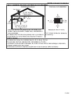
Figure 3: Installation Clearances and Clearances to
Combustibles .............................................................7
Figure 4: Suspension Methods .................................................9
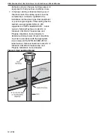
Figure 5: Vent and Roof Detail ................................................ 12
Figure 6: Standard Vented Heater - Vertical and Horizontal
Vent Termination....................................................... 13
Figure 7: Standard Vented Heater - Common Vertical Vent
Termination............................................................... 14
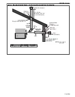
Figure 8: Separated Combustion Heater - Vertical and
Horizontal Vent Termination ..................................... 15
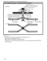
Figure 9: Concentric Vent Box................................................. 15
Figure 10: Concentric Vertical and Horizontal Vent
Termination - Separated Combustion Heater.......... 16
Figure 11: Gas Connection...................................................... 19
Figure 12: Automatic Burner Control Sequence ......................30
Figure 13: Single Stage Gas Valve for Models UHA[X][S]
150 - 400.................................................................31
Figure 14: Two Stage Gas Valve for Models UHA[T][X][S]
150 - 400.................................................................31
Figure 15: Modulating Gas Valve for Models UHA[M][X][S]
150 - 400.................................................................32
Figure 16: LED Diagnostic Codes ...........................................36
There are references in this manual to various trademarks. All trademarks mentioned herein, whether registered or not, are the
property of their respective owners. Rapid Engineering LLC is not sponsored by or affiliated with any of the trademark or registered
trademark owners, and makes no representations about them, their owners, their products or services.
Summary of Contents for UHAM 150
Page 2: ......
Page 4: ......
Page 8: ......
Page 50: ...UHA STANDARD UNIT HEATER INSTALLATION OPERATION AND SERVICE MANUAL 42 of 59 14 1 General ...
Page 65: ...SECTION 16 SPECIFICATIONS 57 of 59 16 4 Dimension Data for Models UHA T M X S 300 400 ...
Page 68: ......
Page 69: ......
Page 70: ......
Page 71: ......
Page 72: ......


