UHA S
TANDARD
U
NIT
H
EATER
I
NSTALLATION
O
PERATION AND
S
ERVICE
M
ANUAL
48 of 59
15.2.2 Burner Injectors for Models UHA[T][M][X][S] 150-400
MODEL
UHA
[T][M][X][S]
150
UHA
[T][M][X][S]
175
UHA
[T][M][X][S]
200
UHA
[T][M][X][S]
225
UHA
[T][M][X][S]
250
UHA
[T][M][X][S]
300
UHA
[T][M][X][S]
350
UHA
[T][M][X][S]
400
Orifice Quantity
7
8
9
10
11
12
14
14
Natural Gas
Orifice Marking
43
43
2.25 mm
2.25 mm
2.25 mm
43
43
40
P/N
91930043
91930043
91930225
91930225
91930225
91930043
91930043
91930040
Propane
Orifice Marking
1.35 mm
1.35 mm
54
54
54
1.45 mm
53
53
P/N
91930135
91930135
91930054
91930054
91930054
91930145
91930053
91930053
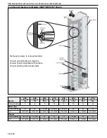
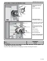
Remove 4 screws to remove manifold.
Ensure gas tight fitting of injectors.
Ensure correct alignment with burners.
Ensure all pipe joints are gas tight.
Summary of Contents for UHAM 150
Page 2: ......
Page 4: ......
Page 8: ......
Page 50: ...UHA STANDARD UNIT HEATER INSTALLATION OPERATION AND SERVICE MANUAL 42 of 59 14 1 General ...
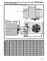
Page 65: ...SECTION 16 SPECIFICATIONS 57 of 59 16 4 Dimension Data for Models UHA T M X S 300 400 ...
Page 68: ......
Page 69: ......
Page 70: ......
Page 71: ......
Page 72: ......


