background image

SECTION 3: C

RITICAL 

C

ONSIDERATIONS

5 of 59

SECTION 3: CRITICAL CONSIDERATIONS
3.1 Basic Information

UHA[T][M][X][S] heaters have automatic ignition 
burners for ON/OFF, HIGH/LOW or modulate within 
the range of HIGH/LOW operation.

3.2 Manufactured Units

Gas-fired, power-vented unit heater with tubular heat 
exchanger. Units shall have a minimum of 82% 
thermal efficiency. The standard unit shall consist of 
a non-separated combustion design with an 
aluminized heat exchanger and single stage gas 
valve. Design and heat exchanger alternatives shall 
be offered as follows:

• Separated Combustion: [S] A separated 

combustion unit shall consist of a sealed 
enclosure with a hinged door. Combustion air 
inlet on rear of heater allows for intake venting 
from outside of heated space to be attached. 
Combustion flue gases shall be ducted from 
outside heated space by ductwork connected to 
unit’s outlet flange.

• Stainless Steel Heat Exchanger: [X] A stainless 

steel heat exchanger unit shall consist of heat 
exchanger tubes, heat exchanger tube supports 
and heat exchanger tube plate produced of 409 
stainless steel. Air inlet temperatures below 40 
°F (4.5 °C) are not recommended for this 
application.

• Two Stage Gas Valve: [T] A two-stage gas valve 

shall allow heater to function in either high or low 
fire.

• Modulating Gas Valve: [M] A modulating gas 

valve shall allow heater to modulate between 
high and low fire.

3.3 Location and Suspension

All models:

• Must be installed indoors.

• Must be installed in a level position with 

horizontal discharge.

• May be mounted on a shelf of non-combustible 

material.

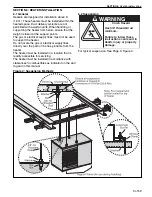
• May be suspended from above (See Page 9, 

Figure ) or from wall brackets of sufficient 
strength to support the heater as listed in the 

Technical Data Table on Page 56, Section 16.2 

and Page 58, Section 16.5.

• Drop rods must be a minimum of 3/8" diameter 

mild steel. Four suspension points (3/8" nuts) 
are located on top of the heater. 

• Must be installed in a manner which allows 

access to all serviceable components.

3.4 Minimum Required Installation Clearances

Clearances around the heater and vent must be as 
indicated on Page 7, Figure 3 and Page 10, Section 
7 t
o ensure access for servicing and correct 
operation.

3.5 Ventilation

It is important to ensure that there is adequate air 
space around the heater to supply air for 
combustion, ventilation and distribution in 
accordance with local and national codes on Page 
10, Section 7. 

3.6 Gas Supply

It is important that the gas supply pipe is sized 
correctly to provide the inlet pressure as stated on 
the heater serial plate. The gas supply pipe and 
electrical connections must not support any of the 
heater's weight. See Page 18, Section 9. 

3.7 Electrical Supply

A permanent 120 V / 1 Ø / 60 Hz electrical supply is 

required for the main electrical power. The heater 
also requires suitable controls in accordance with 
Page 20, Section 10.

3.8 Vent 

Choose heater orientation to allow for the proper 
location of the vent. Each heater must be fitted with 
a correctly sized sealed vent system. 
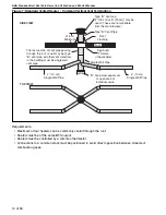
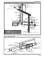
If vented horizontally, no other equipment may be 
connected to the vent. See Page 10, Section 7.

Summary of Contents for UHAT 150

Page 1: ...done by a contractor qualified in the installation and service of gas fired heating equipment or your gas supplier Improper installation adjustment alteration service or maintenance can result in deat...

Page 2: ......

Page 3: ...n respect de ces instructions peut entra ner la mort des blessures corporelles ou des dommages mat riels ATTENTION L installation doit tre effectu e par un installateur prouv contractant qualifi dans...

Page 4: ......

Page 5: ...Series Internal Wiring Diagram for Single Stage Gas Valves 22 10 4 UHA X S Series Ladder Wiring Diagram for Single Stage Gas Valves 23 10 5 UHA T X S Series Internal Wiring Diagram for Two Stage Gas...

Page 6: ...16 4 Dimension Data for Models UHA T M X S 300 400 57 16 5 General Technical Data Table 58 16 6 Technical Data Table 58 SECTION 17 The RAPID UHA Series Warranty 59...

Page 7: ...rtical and Horizontal Vent Termination Separated Combustion Heater 16 Figure 11 Gas Connection 19 Figure 12 Automatic Burner Control Sequence 30 Figure 13 Single Stage Gas Valve for Models UHA X S 150...

Page 8: ......

Page 9: ...and operated under the general concepts of reasonable use and installed using the best building practices This equipment is not intended for use by persons including children with reduced physical sen...

Page 10: ...y Description Part Number Logo Label 91031102 Cut Hazard Label 91010430 Vent Length Label 91039505 Vent to Outdoors Label 91010427 Warning Label 91010429 Rating Plate Label 91010418 Installation Label...

Page 11: ...ber Logo Label 91031102 Cut Hazard Label 91010430 Vent Length Label 91039505 Vent to Outdoors Label 91010427 Warning Label 91010429 Rating Plate Label 91010418 Installation Label 91010431 Instruction...

Page 12: ...033 is illustrated on the back cover Know your model number and installed configuration Model number and installed configuration are found on the heater serial plate and throughout the Installation Op...

Page 13: ...ndoors Must be installed in a level position with horizontal discharge May be mounted on a shelf of non combustible material May be suspended from above See Page 9 Figure or from wall brackets of suff...

Page 14: ...inity of this heater The stated clearances to combustibles represents a surface temperature of 90 F 50 C above room temperature Building materials with a low heat tolerance such as plastics vinyl sidi...

Page 15: ...rs may be mounted at a higher level if destratification fans are installed For Models UHA 150 400 venting directly from top of heater is not applicable For roof terminal vent elbow duct off back of he...

Page 16: ...ision Canada Refer to Natural Gas and Propane Installation Code Standard CSA B149 1 latest revision 5 4 Electrical The heater must be electrically grounded in accordance with the following codes Unite...

Page 17: ...lines must not be used to support the heater Do not locate the gas or electrical supply lines directly over the path of the flue products from the heater The heater must be installed in a location th...

Page 18: ...r that can be opened in any building any non mechanical air supply inlet to any building or of the combustion air inlet of any other piece of equipment 7 2 Vent Installation Maintain clearances to com...

Page 19: ...ed at the roof or wall penetration instead of a thimble Ensure vent manufacturer s clearance from vent material is maintained Seal annular space of the type B 1 vent as well as all joints in the remai...

Page 20: ...gas fired equipment or your local gas supplier If the venting must be resized use appropriate tables in US Appendix G of NFPA 54 ANSI Z223 1 latest revision National Fuel Gas Code US or Standard CSA B...

Page 21: ...al Option Horizontal Option Vent 90 Bend 12 31 cm Minimum from roof to vent termination Vent Termination Listed thimble through combustible wall Flashing By Others 12 31 cm Minimum from wall to vent t...

Page 22: ...ositioned to avoid direct opposition between streams of combustion gases Roof 2 6 m Minimum Type B vent cap 7 18 cm or 8 20 cm may be used These are not available from the manufacurer Roof Flashing Ap...

Page 23: ...0 400 5 13 cm 90502105 4 10 cm Single Wall Vent Pipe By Others Seal joint between single wall and Type B vent with silicone sealant Use 3 sheetmetal screws equally spaced around joint Use 3 sheetmetal...

Page 24: ...m Collar By Others Attach with 3 sheet metal screws 12 31 cm Minimum from roof to combustion air terminal Flashing By Others 12 31 cm Minimum from wall to combustion air terminal Description Part Numb...

Page 25: ...de Combustion Air Supply If outside combustion air supply is required separated combustion model UHA T M X S heaters must be used Caution If the building has a slight negative pressure or corrosive co...

Page 26: ...included in the layout drawing contact the local gas supplier An isolating valve and union connection should be used and fitted into the supply adjacent to the heater A minimum 1 8 NPT plugged tapping...

Page 27: ...Heavy Gauge Pipe Gas Connector Option A Stainless Steel Flexible Gas Connector Do not twist flexible gas connector Ensure all joints are gas tight CAUTION Hold gas nipple securely with pipe wrench whe...

Page 28: ...m thermostat should be mounted on a vibration free wall or column at a height of approximately 5 1 5 m from the floor to measure the ambient temperature It should be clear of both cold drafts and the...

Page 29: ...SECTION 10 WIRING 21 of 59 10 2 Low Voltage Thermostat for Models UHA T M X S 150 400 NOTE Models 300 400 have two axial fans NOTE Electrical supply is located below terminal strip...

Page 30: ...agram for Single Stage Gas Valves NOTE For field wiring into service junction box or if any of the original wire supplied with the heater must be replaced it must be replaced with wiring material havi...

Page 31: ...Valves NOTE For field wiring into service junction box or if any of the original wire supplied with the heater must be replaced it must be replaced with wiring material having a temperature rating of...

Page 32: ...ge Gas Valves 1 W2 HIGH LOW CONTROL HIGH LOW COMMON NOTE For field wiring into service junction box or if any of the original wire supplied with the heater must be replaced it must be replaced with wi...

Page 33: ...s HIGH STAGE NOTE For field wiring into service junction box or if any of the original wire supplied with the heater must be replaced it must be replaced with wiring material having a temperature rati...

Page 34: ...Diagram for Modulating Gas Valves NOTE For field wiring into service junction box or if any of the original wire supplied with the heater must be replaced it must be replaced with wiring material havi...

Page 35: ...lves NOTE For field wiring into service junction box or if any of the original wire supplied with the heater must be replaced it must be replaced with wiring material having a temperature rating of at...

Page 36: ...LLATION OPERATION AND SERVICE MANUAL 28 of 59 10 9 Electrical Connection to the Heater Note Junction box is not provided with heater Conduit can also be attached directly to heater with wire junction...

Page 37: ...gas installation including the gas meter must be inspected tested for gas tightness and purged in accordance with local and national codes Ensure that the air is fully purged from the heater inlet pi...

Page 38: ...ure 12 There will be no ignition of the burner and lockout will occur which proves the controls are operating correctly Figure 12 Automatic Burner Control Sequence Burner Sequence for Ignition Control...

Page 39: ...Inlet I l t P TOP VIEW END VIEW Description Part Number Gas Valve 150 250 NG 90032505 Gas Valve 150 250 LP 90032506 Gas Valve 300 400 NG 90032520 Gas Valve 300 400 LP 90032521 PSI IN C ON OFF LO HI Re...

Page 40: ...f 59 Figure 15 Modulating Gas Valve for Models UHA M X S 150 400 Description Part Number Gas Valve 150 250 NG 90032505 Gas Valve 150 250 LP 90032506 Gas Valve 300 400 NG 90032520 Gas Valve 300 400 LP...

Page 41: ...ve To adjust high fire burner pressure remove regulator cover from Honeywell single stage gas valve and turn regulator adjustment screw to set required burner pressure as stated in the Technical Data...

Page 42: ...ater for service or during off season 11 5 External Controls External controls may include time switch interlock switch room thermostat and frost thermostat Operate each control to ensure that they fu...

Page 43: ...ely The fan will continue to run for 90 seconds To restart turn the thermostat on or above room temperature 12 3 Simple Troubleshooting Some possible reasons for the heater not operating are 1 Gas sup...

Page 44: ...AULT MODE Slow Flash Normal Operation No call for heat Fast Flash Normal Operation Call for heat 2 Flashes Ignition Lockout No flame detected 3 Flashes Airflow Fault Pressure switch open or closed 4 F...

Page 45: ...2 Remove the filler panel 10 screws to fully access the burner assembly See Page 47 Section 15 2 1 3 Remove burner assembly from cabinet via six screws See Page 47 Section 15 2 1 Electrode and flame p...

Page 46: ...take components to ensure they are in good condition gas tight and corrosion free 13 8 Maintenance Checklist Installation Code and Annual Inspections All installations and service of RAPID equipment m...

Page 47: ...ow Make sure it is clean and free of cracks or holes Clean and replace as required Flue Blower Scroll Wheel and Motor Compressed air or a vacuum cleaner may be used to clean dust and dirt Inshot Burne...

Page 48: ...ION OPERATION AND SERVICE MANUAL 40 of 59 Wall Tag If a wall tag is present make sure it is legible and accurate Please contact Rapid Engineering LLC or your RAPID independent distributor if you need...

Page 49: ...e to follow these instructions can result in death electric shock injury or property damage Burn Hazard Allow heater to cool before service Tubing may still be hot after operation Explosion Hazard Tur...

Page 50: ...UHA STANDARD UNIT HEATER INSTALLATION OPERATION AND SERVICE MANUAL 42 of 59 14 1 General...

Page 51: ...14 2 Troubleshooting For Automatic Ignition Burner Systems For your safety and optimum heater performance use only replacement parts sold and supplied by Rapid Engineering LLC Conduct start up proced...

Page 52: ...r or replace as required Is inlet burner gas pressure correct Is live and neutral polarity correct Is flame probe circuit correct Is there a current flowing in the flame probe circuit with no flame pr...

Page 53: ...valve rise when valve turns on No Yes Is gas pressure at inlet of the valve correct for gas type Note pressure found No Yes START If problems persist contact Rapid Engineering LLC at www rapidenginee...

Page 54: ...ECT GAS VALVE IS USED WHEN REPLACING THESE CONTROLS Carbon Monoxide Hazard WARNING Use only genuine RAPID replacement parts per this installation operation and service manual Failure to follow these i...

Page 55: ...ent with Hinged Door Removed Before burner removal remove the 10 screws holding the filler panel on and remove the filler panel NOTE Models UHA 300 400 have two axial fans Side View of Burner Compartm...

Page 56: ...rifice Quantity 7 8 9 10 11 12 14 14 Natural Gas Orifice Marking 43 43 2 25 mm 2 25 mm 2 25 mm 43 43 40 P N 91930043 91930043 91930225 91930225 91930225 91930043 91930043 91930040 Propane Orifice Mark...

Page 57: ...Burners UHA T M X S 200 92000000 9 Inshot Burners UHA T M X S 225 92000000 10 Inshot Burners UHA T M X S 250 92000000 11 Inshot Burners UHA T M X S 300 92000000 12 Inshot Burners UHA T M X S 350 92000...

Page 58: ...de of aluminized steel 409 stainless steel The tube supports are made of aluminized steel 409 stainless steel 15 5 Louvers and Louver Spring The louvers for standard range models UHA T M X S 150 UHA T...

Page 59: ...ng an flue blower See Page 29 Section 11 MODEL UHA T M X S 150 300 Flue Blower P N 90710403 Remove screws securing outlet flange to the flue adapter Refit in reverse order Disconnect electrical connec...

Page 60: ...402 Vent Box Outlet Gasket Flue Blower Vent Box screws Flue Adapter Flue Adapter to Flue Blower screw Rear Panel Hole Disconnect electrical connections at plug in tabs Mounting Plate to Vent Box screw...

Page 61: ...s supplied completely assembled and balanced Carbon Monoxide Hazard Use correct pressure switch specified for each model Use of incorrect pressure switch or disabling pressure switch circuit could cau...

Page 62: ...ly genuine replacement parts sold and supplied by Rapid Engineering LLC 15 11 Limit Switches 15 11 1 Removal and Replacement 1 Remove the electrical connections to the switch 2 Unscrew the two screws...

Page 63: ...25 5 64 8 25 5 64 8 D in cm 17 6 44 7 17 6 44 7 17 6 44 7 17 6 44 7 17 6 44 7 E in cm 19 4 49 3 19 4 49 3 19 4 49 3 19 4 49 3 19 4 49 3 F in cm 30 0 76 2 30 0 76 2 32 0 81 3 32 0 81 3 32 0 81 3 G in c...

Page 64: ...1 40 1 40 1 Weight Net lbs kg 217 98 4 237 107 5 255 115 7 265 120 2 270 122 5 Model UHA T M X S 150 UHA T M X S 175 UHA T M X S 200 UHA T M X S 225 UHA T M X S 250 Total Input High Fire Btu h x 1000...

Page 65: ...SECTION 16 SPECIFICATIONS 57 of 59 16 4 Dimension Data for Models UHA T M X S 300 400...

Page 66: ...7 N in cm 6 5 16 5 6 5 16 5 6 5 16 5 Model UHA T M X S 300 UHA T M X S 350 UHA T M X S 400 Full Load Amps 120 V A 11 6 11 6 11 6 Air Volume CFM 4663 4663 4663 Flue and Air Intake Flue Intake Size in...

Page 67: ...ta plate and or serial number are removed defaced modified or altered in any way The ownership of the RAPID UHA Series is moved or transferred This warranty is nontransferable Rapid Engineering LLC is...

Page 68: ......

Page 69: ......

Page 70: ......

Page 71: ......

Page 72: ......

Reviews: