


Rapid Spray FieldLink Operators Handbook
Rapid Spray Equipment by Rapid Spray
REV OCT 2019
13
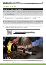
FITTING PTO SHAFT
STEP-BY-STEP PTO SHAFT CUTTING GUIDE
1.
Install the PTO shaft onto the tractor and FieldLink while shaft is horizontal and at it's
shortest length. If you cannot fit the shaft at this point as it is too long, it will need to
be shortened further.
2.
Without running the PTO, lower the FieldLink to the ground and check the angle of
the shaft and universal joints. This angle should not exceed 25° at rest.
3.
Raise the FieldLink to the maximum operating height and check the angle of the shaft
and universal joints. This angle should not exceed 17° for continuous operations.
4.
Lastly, check the overlap of the shaft end exceeds 50% of the total length of the shaft
operation to prevent premature failure of the shaft.
See
https://resources.rapidspray.net/blog/how-to-
correctly-size-your-3pl-shaft
for full guide with images.


