background image

WARRANTY REGISTRATION

You can register online at www.rapidspray.net/resources/warranty-registration or 

complete all the details below and post this form back to: 

Rapid Spray, PO Box 3119, Singleton NSW 2330

Model  ......................................................  Serial No  .....................................................

Purchased From  ............................................................................................................ 

(Dealer Name & Town)

Purchaser’s Name  .........................................................................................................

Purchaser’s Address  ......................................................................................................

.........................................................................................................................................

Purchaser’s Phone Number  ..........................................................................................

Disclaimer: If you don’t want us to keep you informed of new products, please tick 
the following circle:

To help us help you further, please complete the following: 
Purchaser’s Age

          Up to 25
          25 - 40 
          41 - 55
          Over 55

What influenced you to purchase a Rapid Spray product? 

          Received Catalogue   


Better features than competitor product

          Newspaper advertisement   

Quality & reliability

          Magazine advertisement 


Price

          Dealer recommendation 


Past experience with Rapid Spray products

          Friends recommendation 


Other......................................................

Principal Usage

          Commercial farm 


Town council

          Hobby farm  


Hire company

          Industrial   


Home

          Other...............................................................

What other Rapid Spray products do you use? 

          Spray tanks  


Boom sprayers

          Cartage tanks 


Bertolini pumps & controllers

          Diesel tanks  


Inter knapsacks | Compression sprayers

          Fire fighting  


Other......................................................

Summary of Contents for FIELDLINK ECO

Page 1: ...FIELDLINK OPERATORS HANDBOOK FIELDLINK ECO FIELDLINK PRO 400L 600L 800L ...

Page 2: ...un Holder 07 Mounting Controls 08 Mounting Electric Controls 09 Mounting Boom 10 Mounting Hose Reel Manual Buddy Smart Reel PTO Shaft Instructions 11 Warnings 12 Correctly Size PTO Shaft 13 Fitting PTO Shaft 14 Hitching FieldLink to Tractor 15 Filling Mixing 16 Calibration 17 Spraying 19 Cleaning Maintenance 20 FieldLink Breakdown 23 Bertolini Poly 2073 Pump 25 Warranty 27 Warranty Registration ...

Page 3: ...een designed for effortless spraying of herbicides and pesticides The design of the tank enables the unit to be mounted onto tractors of varying sizes from approximately 35HP and greater DISCLAIMER In line with our policy of continuous improvement the weights dimensions and design may change slightly from what is shown in the book Rapid Spray accepts no liability for the unsafe operation of this u...

Page 4: ...vironmental and work place health and safety regulations 6 Personal Protection Equipment must still be worn while decontaminating your hose reel as per warning 3 above 7 Improper or careless use of this sprayer can cause serious injury Minors should never be allowed to use this sprayer This sprayer should not be used when bystanders or animals are in the area This sprayer should never be used whil...

Page 5: ... in the Material Safety Data Sheet coveralls gloves safety footwear glasses and respirator follow safe manual handling procedures as above 3 Mix chemicals and fill spray tank units As above spray drift chemical spillage emission of vapours or flammability weather untrained visitors Med As above user trained in the state s chemical mixing and administration course e g Chem Cert follow the relevant ...

Page 6: ...drops fluctuates during standard operation 1 Restriction on suction line 2 Pump sucking air 3 Plugged filter 4 Damaged regulator 1 Inspect tank and suction lines and remove restriction 2 Tighten fittings 3 Remove and clean filter mesh and housing 4 Remove regulator stem and inspect for broken parts pieces Pressure gauge not registering 1 Plugged with debris 1 Unthread check and clean pressure gaug...

Page 7: ...FieldLink you may need to assemble a few of the components before commencing spraying If you have any queries or questions further to the instructions on the following pages please feel free to give one of our friendly customer service members a call on 1800 011 000 and they will be happy to guide you through the steps NOTES ...

Page 8: ... Attach hose clips to front using screws supplied Wrap hose around hangers and mount gun Item No Part No Qty Description 1 CHS10M02546Z 4 M10 Bolt x 20mm 2 CHWF10MHZ 4 M10 Washer 3 CHWS10MS 4 M10 Spring Washer 4 CHLM05M025Z 2 M5 x Pan Phillips Head x 25mm 5 CHWS05MS 2 M5 Washer 6 CHNN05MZ 2 M5 Nylock Nut 7 CHCLP12MMX2 Pack 2 Lance Clips 8 ASFL00600FLHH 2 Hose Hangers 1 2 8 6 5 7 4 3 ...

Page 9: ...8 x 25mm Bolt 4 CHWF08MHZ 8 M8 Washer 5 CHNN08MZ 4 M8 Nyloc Nut 6 CHS06M02546Z 4 M6 x 25mm Bolt 7 CHWS06MHZ 4 M6 Spring Washer 8 CHWF06MHZ 4 M6 Washer 1 Attach Mounting Brackets Regulator Attach mounting bracket using bolts supplied Mount regulator facing forward with bolts as supplied 2 Attach Hoses Mount three black hoses in order using pin clips Mount clear return hose using large pin clip Ensu...

Page 10: ...ollow regulator mounting instructions as per Mounting Regulator on page 7 2 Attach Electrical Cables Attach control box wires labeled 1 3 to each section valve Insert screws to hold in place NOTE Do not attach wire labeled P 3 In Cab Control Box Using clips supplied install mount control box in the cab of the tractor for easy reach ...

Page 11: ...P 4 M10 x 30mm Cup Head Bolt 4 CHWF10MHZ 20 M10 Washer 5 CHNN10MZ 6 M10 Nyloc Bolt 6 CHS10M03046Z 4 M10 x 30mm Bolt 7 CHNH10M88Z 8 M10 Nut 8 1 Boom 9 CHUS10M050X060 4 M10 U Bolt 1 Slotted Mounting Attachment NOTE Component 1 will be already attached to frame Attach universal z brackets Loosely fit slide bolts 2 Mount Boom Attach Hoses Slide boom into slotted attachment set height of boom and tight...

Page 12: ...mm Bolt 5 CHWS06MHZ 4 4 M10 Spring Washer 6 CHWF10MHZ 8 4 M10 Washer 1 Attach Mounting Plate and Hose Reel Using bolts supplied mount Manual hose reel straight onto tank No mounting plate required Attach mounting plate to the FieldLink tank first then the Buddy Smart Reel using the bolts supplied 2 Attach Hoses Run supplied hose from reel to spare outlet on controls Secure hose tail using pin clip...

Page 13: ...o not expose guarded parts of the shaft by cutting or enlarging grease access holes PTO shafts and safety clutches have to match the power take off and the machine type See the instructions with your machine for recommended type and size of shaft and clutches Overload can cause damage Do not operate above recommended speeds No device e g adapters shall be installed between the tractor PTO and the ...

Page 14: ... tractor If the shaft is already shorter than this ensure that minimum of 50 of total shaft length overlaps when in operation 6 Amount to cut off shaft NEW SHAFT Step 4 INSIDE GROOVES Step 2 76mm CUT TOTAL 1194 890 76 380 7 To find the length to cut of each end of shaft divide the CUT TOTAL from Step 7 by two Cut this length off each shaft CUT TOTAL 2 CUT LENGTH 380 2 190mm 8 Cut the CUT LENGTH of...

Page 15: ...ithout running the PTO lower the FieldLink to the ground and check the angle of the shaft and universal joints This angle should not exceed 25 at rest 3 Raise the FieldLink to the maximum operating height and check the angle of the shaft and universal joints This angle should not exceed 17 for continuous operations 4 Lastly check the overlap of the shaft end exceeds 50 of the total length of the s...

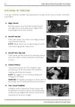
Page 16: ...for 3 point locking system instructions 3 Insert Pin to Top Link Hook up the top link to the third mounting point at the centre of the unit and insert the correct sized lock pin 4 Connect Pump Connect the pump to the PTO shaft and hook on the torque chain to keep the PTO shaft from rotating with the pump rotation NOTE See pages 6 8 on correctly cutting and fitting your PTO shaft WARNING PTO shafts...

Page 17: ...ition Turn regulator valve knob in an anti clockwise direction to reduce pressure to O bar Engage PTO shaft to commence pumping and fluid circulation Now add the pesticides as measured correctly before to the spray tank while still agitating Rinse out the measuring jug and pour all rinsing s into the spray tank Safely dispose of empty containers in compliance with current regulations Top up the ta...

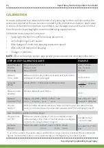
Page 18: ...re 50L hectare Medium Measure Time 100m Measure time to spray 100m in seconds over land similar to that which will be sprayed 41 9 seconds Calculate SPEED Speed km h 360 divided by time seconds 360 8 6km h 41 9 Measure nozzle SPACING Distance between each nozzle 0 5m Measure L min OUTPUT Output VOLUME x SPEED x SPACE 600 L min L hectare km h metre 200 x 8 6 x 0 5 600 Output 1 433L min Choose NOZZL...

Page 19: ...Work Rates Speed of operation Water points or nurse tanks Rate of travel Swath width Spray volume applied 4 Wind and drift Wind speed Wind direction Airspeed at boom height Wind direction and drift is controlled by Reducing nozzle height Reducing pressure and using larger nozzles Fit low drift nozzles producing larger droplets NOTE Avoid spraying on still warm days or during the night as convectio...

Page 20: ...rkers or tram lines Where large obstacles exist in the middle of an area to be sprayed mark out and spray the area like a separate headland The perimeter of the field should be sprayed first The width of two swaths will give adequate turning space at the ends of spray runs Never spray while turning 6 Maintain constant speed when spraying Should you need to increase your spraying speed larger deliv...

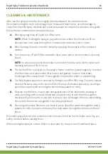
Page 21: ...the sprayer frame must be cleaned regularly Unscrew the filter cover and remove the filter screen and gasket Soak in clean water brushing with a nozzle brush Ensure gasket is in position when re assembling 5 The filter basket strainer is removed by lifting it out of the filler ring Clean the basket strainer the same way as the suction filter Replace the basket strainer by exerting a quick downward...

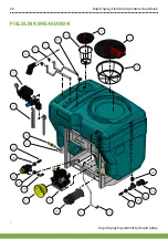
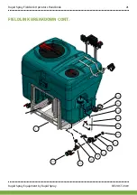
Page 22: ...Rapid Spray FieldLink Operators Handbook Rapid Spray Equipment by Rapid Spray 20 FIELDLINK BREAKDOWN 7 15 6 16 19 2 5 13 3 4 29 1 27 26 14 26 28 17 9 18 11 10 27 26 23 24 22 FIELDLINK BREAKDOWN ...

Page 23: ...Rapid Spray FieldLink Operators Handbook Rapid Spray Equipment by Rapid Spray REV OCT 2019 21 1 24 23 22 27 26 21 30 22 25 12 10 8 20 FIELDLINK BREAKDOWN CONT ...

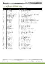
Page 24: ...2B 2 3 8 12mm 90 Hosetail 11 CUVC16MM 1 16mm Clear Vinyl Hose 12 CUVC16MM 1 16mm Clear Vinyl Hose 13 AHG109 1 Spray Gun 14 ATPFSV032T32T 1 Suction Filter with Shut Off Valve 15 ARK400 1 Basket Filter to suit 450mm Lid 16 ARK200 1 Basket Filter to suit 250mm Lid 17 CBP311468322 1 PTO Shield for Poly 2073 large 18 AXPD001 1 Manual Holder 19 CYGRE032 1 1 1 4 Uniseal for 32mm Pipe 20 ARLP100 1 100mm S...

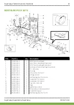
Page 25: ...40 36 2 3 HPS Piston Diaphragm optional 1 95 0040 00 2 3 Desmopan Piston Diaphragm optional 2 28 9809 97 3 6 S S Valve Assy 3 53 0007 32 2 1 Housing 4 80 2143 10 2 1 Oil Seal Dia 35 x 52 x 7 5 80 3310 00 2 1 O Ring 4 0 x 82 6 81 2837 00 2 1 Ball Bearing Dia 35 x 62 x 14 7 63 0009 26 2 1 Crankshaft VS Version 11 63 0016 26 2 1 Crankshaft VA Version 12 80 6475 00 2 1 Tab 6 36 x 6 36 x 38 13 26 0047 ...

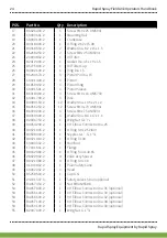
Page 26: ...crew M10 x 70 UNI5931 36 86 3002 00 2 3 Screw M8 x 75 UNI5931 37 84 3693 00 2 3 Washer Dia 8 4 x 17 x 1 6 38 82 0067 50 2 1 Wing Nut G 1 1 4 39 84 0542 40 2 1 90 Elbow Connector Dia 25 40 80 3219 05 2 1 O Ring 3 0 x 25 Viton 41 83 5089 00 2 1 Nipples G 1 G 1 1 4 42 80 3219 10 2 1 O Ring 3 x 30 43 63 0003 32 2 1 Manifold 44 17 0016 61 2 1 Flange 45 80 3320 80 2 6 O Ring 5 34 x 40 65 46 28 0229 32 2...

Page 27: ...laims by their customers in excess of the obligations of RAPID SPRAY expressly set forth herein NOTE All tank and spray systems must have their warranty activated by returning warranty card located at the end of this document or registering online within 21 days of purchase by the end user The Warranty All products sold by RAPID SPRAY are guaranteed to be free from defect in materials workmanship ...

Page 28: ...d connections damaged by corrosive chemicals dirt and sand excessive heat moisture or other environmental impacts Warranty determination on these type of failures will be made by RAPID SPRAY only after inspection of the failed component Inability Unsuitability In no event shall RAPID SPRAY be liable to any person for indirect or consequential damages or for injury or commercial loss resulting from...

Page 29: ...u further please complete the following Purchaser s Age Up to 25 25 40 41 55 Over 55 What influenced you to purchase a Rapid Spray product Received Catalogue Better features than competitor product Newspaper advertisement Quality reliability Magazine advertisement Price Dealer recommendation Past experience with Rapid Spray products Friends recommendation Other Principal Usage Commercial farm Town...

Page 30: ...Rapid Spray FieldLink Operators Handbook Rapid Spray Equipment by Rapid Spray 28 This page has been left blank intentionally ...

Page 31: ...Rapid Spray FieldLink Operators Handbook Rapid Spray Equipment by Rapid Spray REV OCT 2019 29 NOTES ...

Page 32: ...all us on 1800 011 000 or visit www rapidspray net 35 Enterprise Cres Singleton NSW 2330 PO BOX 3119 Singleton NSW 2330 Telephone 1800 011 000 Facsimile 02 6571 2951 Rapid Spray Liquid Management Systems ...

Reviews: