background image

P1

Max Screen Size:  70”


CAUTION: 

THE MAXIMUM LOADING 

WEIGHT IS 125 LBS.  USE WITH PRODUCTS 

HEAVIER THAN THE MAXIMUM WEIGHT 

INDICATED MAY RESULT IN INSTABILITY AND 

POSSIBLE PERSONAL INJURY.

!

RVM-64CM125

TV Ceiling Mount

INSTRUCTION MANUAL

MANUAL DE INSTRUCCIONES
MANUEL D’INSTRUCTIONS

V1

Reduce

Reuse

Recyle

Summary of Contents for RVM-64CM125

Page 1: ... WEIGHT IS 125 LBS USE WITH PRODUCTS HEAVIER THAN THE MAXIMUM WEIGHT INDICATED MAY RESULT IN INSTABILITY AND POSSIBLE PERSONAL INJURY RVM 64CM125 TV Ceiling Mount INSTRUCTION MANUAL MANUAL DE INSTRUCCIONES MANUEL D INSTRUCTIONS V1 Reduce Reuse Recyle ...

Page 2: ...rito a info rapidvideomounts com No instale ni ensamble el producto si éste o las piezas suministradas presentaran daños o si faltara algún elemento Las piezas incluidas están diseñadas para ser instaladas en paredes con paneles de madera o en paredes de hormigón Se define como pared con montantes de madera aquélla conformada por montantes de madera de 51 mm 2 pulgadas de ancho por 102 mm 4 pulgad...

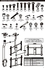
Page 3: ... H Maximum 600mm x 400mm W X H Product Components Contents Qty Description A 1 Ceiling Plate B 1 Universal Monitor Plate C 1 Pipe Assembly Product Components Contents Qty Description A 1 B 1 Universal Monitor Plate C 1 C B A 11 5mm SPACER X 4 10 SQUARE WASHER X 4 6 5 7 2 1 3 M5 x 12 X 4 M6 x 15 X 4 M8 x 15 X 4 M5 x 30 X 4 M6 x 30 X 4 M8 x 30 X 4 4 8 M4 x 12 X 4 M4 x 30 X 4 10mm SPACER X 4 12 15 ST...

Page 4: ...or Connectez l adaptateur au moniteur STEP 1 CURVED BACK TV UNIVERSAL MONITOR PLATE X4 or or or 1 2 3 4 10 10 Connect Universal Monitor Plate to flat panel Conecte el adaptador al monitor Connectez l adaptateur au moniteur 10 12 11 X4 Spacers can also be used to provide clearance for cables and connectors 5 6 7 8 9 ...

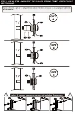
Page 5: ...hree options for using additional washers if hardware screws are too long to properly tighten into back of television STEP 1 USE M8 STEEL WASHER IF THE PHILLIPS SCREWS FROM THE MONITOR KIT ARE TOO LONG 12 12 11 11 select the proper spacers or spacer suit as below if necessary ...

Page 6: ...P6 STEP 1 CENTER UNIVERSAL MONITOR PLATE Monitor Plate must be centered horizontal plane on back of TV X2 Secure vertical rails to horizontal chrome rod on Monitor Plate with pre installed screws 17 ...

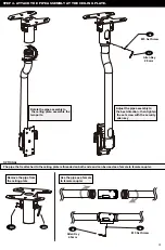
Page 7: ...P7 STEP 2 ASSEMBLE THE CEILING MOUNT A10 A8 A7 A9 A9 A8 15 14 A3 A4 A9 ...

Page 8: ...P8 STEP 3 WOOD STUD INSTALLATION B A X2 Wood Pilot Pilot Hole Size Pilot Drill Depth 7 32 inch 2 75 inch 5 5 mm 70 mm 13 14 ...

Page 9: ...he best direction then tighten the set screw with the security allen key Rotate the pipe assembly to the ceiling plate assemble the two parts The pipe that is attached to the ceiling plate is threaded on both ends and can be used as a female to female coupler OPTIONAL A3 A4 Remove the pipe from the ceiling plate Use the pipe as a female to female coupler ...

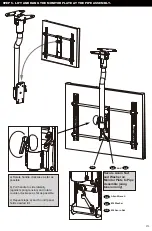
Page 10: ...Washer on Monitor Plate to Pipe Assemble snug tension only Allen Wrench A6 M6 Acorn Nut A5 M6 Washer a Rotate handle clockwise as far as possible b Pull handle to side laterally against spring tension and rotate counter clockwise as far as possible c Repeat steps a and b until panel holds desired tilt ...

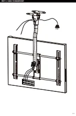
Page 11: ...P11 STEP 6 CABLE MANAGEMENT ...

Page 12: ...onsable en casos en los que no se hayan seguido las instrucciones proporcionadas por RAPID VIDEO MOUNTS En la medida en que la ley lo permita RAPID VIDEO MOUNTS no se hace responsable de ninguna otra garantía expresa o implícita incluso las garantías de aptitud para un fin determinado o de comercialización RAPID VIDEO MOUNTS no se hace responsable de ningún tipo de daños causados por el uso de los...

Reviews: