SECTION 1
8
: S
EQUENCE
OF
O
PERATION
115 of 147
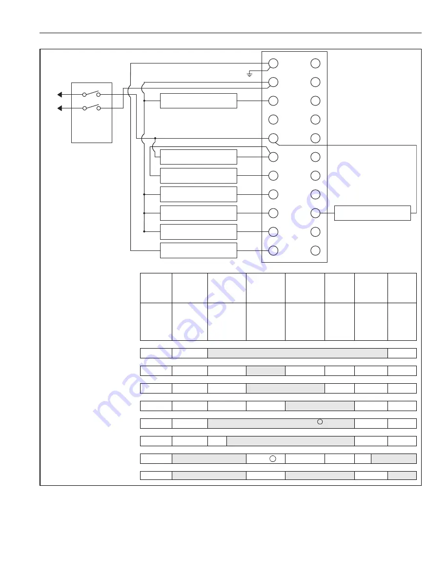
FIGURE 75: RM7
8
97 Flame Control (2020 - 2030)
G
L2
3
4
5
6
7
8
9
10
F
22
21
20
19
18
17
16
15
14
13
12
LINE VOLTAGE ALARM
BURNER CONTROLLER /
LIMITS
10SEC. INTERUPTED
PILOT / IGNITION
MAIN VALVE
IGNITION
FLAME DETECTOR
PRE-IGNITION INTERLOCK
L1
L2
MASTER
SWITCH
RUNNING INTERLOCK
(INC. AIRFLOW SWITCH)
LED Display
Initiate
(Initial
Powerup
only
Standby
Prepur
g
e
(7 Sec)
Pilot Flame
Establishin
g
Period
(10 Sec)
Main Flame
Establishin
g
Period
Run
Postpur
g
e Standby
Po
w
er
Po
w
er
Po
w
er
Pilot
Flame
Main
Alarm
Po
w
er
Pilot
Flame
Main
Alarm
Po
w
er
Pilot
Flame
Main
Alarm
Po
w
er
Pilot
Flame
Main
Alarm
Po
w
er
Po
w
er
Burner
B
u
rner/Blo
w
er Motor
Ignition
Interr
u
pt/Pilot
Main Val
v
e
»
Operatin
g
Controls and Interlocks
Limits and B
u
rner Controller Closed
L1
to
R
u
nning Interlock
to
Preignition Interlock Closed
to
20
PII
Flame Si
g
nal
Safe Start Check
Flame Pro
v
ing
SSC
Summary of Contents for 2005
Page 2: ......
Page 4: ......
Page 8: ......
Page 10: ......
Page 31: ...SECTION 7 ROOF CURB 21 of 147 FIGURE 12 Curb Mounting Air Handler Roof Curb Fastening Detail...
Page 154: ...B SERIES INSTALLATION OPERATION AND SERVICE MANUAL 144 of 147...
Page 158: ......
Page 160: ......
Page 161: ......
Page 162: ......


