B-S
ERIES
I
NSTALLATION
, O
PERATION
AND
S
ERVICE
M
ANUAL
22 of 147
SECTION
8
: UPRIGHT STAND
A stand can be
u
sed
w
hen an
u
pright air handler is to
be installed on a concrete slab or on the floor. The
stand for model 2005 is 30" (76.2 cm) tall; stands for
models 2010 and 2010B are a
v
ailable at 53" (134.6
cm) or 72" (182.9 cm) tall; stands for models 2020
and 2030 are 72"(182.9 cm) tall. The stand m
u
st first
be fastened to the concrete slab or floor before the air
handler is mo
u
nted.
8
.1 Upri
g
ht Stand Installation
To attach the stand to a concrete slab, it m
u
st be
sec
u
red
w
ith the
u
se of st
u
ds, embedded in the
concrete. Fo
u
r 5/8" st
u
ds (minim
u
m) m
u
st be
installed in the slab, one for each corner of the stand.
The stand has fo
u
r 11/16" (17.4 mm) holes drilled
thro
u
gh the stand pads.
.
Fasten the stand to the slab
w
ith fo
u
r 5/8" hex n
u
ts
and lock
w
ashers (pro
v
ided by others).
8
.2 Attachin
g
Air Handler to Stand
Once the stand is sec
u
red to a concrete slab, the air
handler may be placed on the stand. Prior to lifting
the air handler, apply the foam tape and remo
v
e the
attaching hard
w
are as described belo
w
. The ½"
(12.7 mm) thick do
u
ble-sided
u
rethane foam tape
(pro
v
ided by others) m
u
st be applied to the top edge
of the stand. The bolts on the air handler that
correspond to the attaching location of the mo
u
nting
stand m
u
st be remo
v
ed and sa
v
ed for re-installation
to sec
u
re the air handler to the stand. Lift the air
handler on to the mo
u
nting stand.
for safe lifting practices. Once the air
handler is placed on the stand, sec
u
re it
w
ith the
attaching hard
w
are that
w
as remo
v
ed prior to lifting it
in to place per recommended torq
u
e settings.
(2005) and
(2010 - 2030). After placing the
air handler on the mo
u
nting stand, seems bet
w
een
the mo
u
nting stand and the air handler m
u
st be
properly ca
u
lked (ca
u
lk pro
v
ided by others).
NOTE:
If
u
sing a filter section
w
ith an
u
pright air
handler and stand, the filter section m
u
st be set into
the stand before the air handler is mo
u
nted on the
stand. The 1/2" (12.7 cm) thick do
u
ble-sided
u
rethane foam tape sho
u
ld be applied bet
w
een the
stand and the filter section.
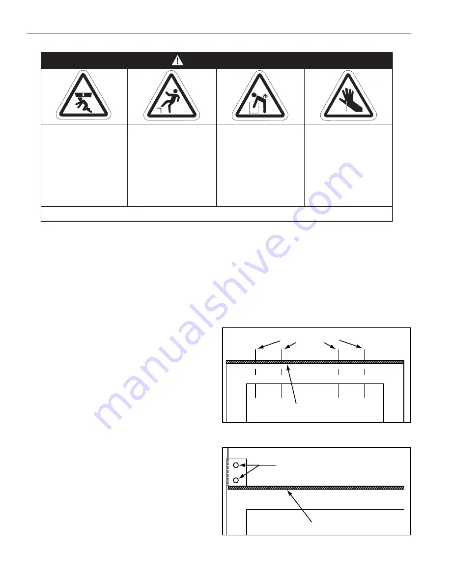
FIGURE 13: Upri
g
ht Stand Detail (2005)
FIGURE 14: Upri
g
ht Stand Detail (2010 - 2030)
Crush Hazard
Use proper lifting
equipment and
practices.
Falling Hazard
Use proper safety
equipment and prac-
tices to avoid falling.
Severe Injury Hazard
Use proper lifting
practices and equip-
ment.
Equipment and
accessories are
heavy.
Cut/Pinch Hazard
Wear protective gear
during installation,
operation and
service.
Edges are sharp.
WARNING
Failure to follow these instructions can result in death, injury or property damage.
Foam Tape
Upright Stand
Attaching Locations
Foam Tape
Upright Stand
Attaching Location
Summary of Contents for 2005
Page 2: ......
Page 4: ......
Page 8: ......
Page 10: ......
Page 31: ...SECTION 7 ROOF CURB 21 of 147 FIGURE 12 Curb Mounting Air Handler Roof Curb Fastening Detail...
Page 154: ...B SERIES INSTALLATION OPERATION AND SERVICE MANUAL 144 of 147...
Page 158: ......
Page 160: ......
Page 161: ......
Page 162: ......


