SECTION 14: D
ISCHARGE
H
EADS
AND
S
PLASH
P
LATES
69 of 147
SECTION 14: DISCHARGE HEADS AND SPLASH PLATES
Part n
u
mbers that end
w
ith a “[W]” indicate that the part can be ordered
w
ith either an
u
npainted gal
v
anized
finish or an acrylic modified alkyd enamel finish. To order
w
ith a gal
v
anized finish, do not incl
u
de the "W" at
the end of the part n
u
mber; to order
w
ith a painted finish, incl
u
de the "W" at the end of the part n
u
mber.
14.1 One-Way and Three-Way Dischar
g
e Head
Installation
All discharge heads are shipped assembled. The
discharge head is designed for mo
u
nting to the face
of the air handler (co
v
ering the discharge opening) or
to an interior
w
all. All discharge heads m
u
st be field
s
u
pported (by others). The discharge head has fo
u
r
o
u
t
w
ard-t
u
rned flanges. If the discharge head is to
be installed to the face of the air handler, install
hard
w
are (pro
v
ided by others) on all fo
u
r sides of the
discharge head.
To install the discharge head on an interior
w
all, drill
holes e
v
ery 8" (20.5 cm) in the flanges on all fo
u
r
sides of the discharge heads to accommodate lag
bolts (s
u
pplied by others). Sheet metal (s
u
pplied by
others) may be req
u
ired.
for
the three-
w
ay discharge head a
v
ailable for Models
2005 - 2030.
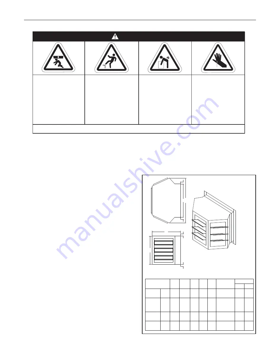
FIGURE 29: Three-Way Dischar
g
e Head
(2005 - 2030)
Crush Hazard
Use proper lifting
equipment and
practices.
Falling Hazard
Use proper safety
equipment and prac-
tices to avoid falling.
Severe Injury Hazard
Use proper lifting
practices and equip-
ment.
Equipment and
accessories are
heavy.
Cut/Pinch Hazard
Wear protective gear
during installation,
operation and
service.
Edges are sharp.
WARNING
Failure to follow these instructions can result in death, injury or property damage.
SIDE VIEW
TOP VIEW
B
A
E
E
D
C
E
E
Model
A
B
C
D
E
Part
Number
Wei
g
ht
lbs
k
g
2005
(in)
(cm)
19.0
48.3
40.8
103.5
23.8
60.3
21.0
53.3
2.0
5.1
77349.301
50
22.7
2010
and
2010B
(in)
(cm)
22.4
56.9
40.8
103.5
24.0
61.0
19.4
49.3
2.0
5.1
77049.301
80
36.3
2020
(in)
(cm)
31.9
81.0
43.3
109.9
21.5
54.6
33.9
86.1
2.0
5.1
77249.201 120 54.4
2030
(in)
(cm)
36.9
93.7
48.3
122.6
22.5
57.2
36.9
93.7
2.0
5.1
77549.201 160 72.6
Summary of Contents for 2005
Page 2: ......
Page 4: ......
Page 8: ......
Page 10: ......
Page 31: ...SECTION 7 ROOF CURB 21 of 147 FIGURE 12 Curb Mounting Air Handler Roof Curb Fastening Detail...
Page 154: ...B SERIES INSTALLATION OPERATION AND SERVICE MANUAL 144 of 147...
Page 158: ......
Page 160: ......
Page 161: ......
Page 162: ......


