B-S
ERIES
I
NSTALLATION
, O
PERATION
AND
S
ERVICE
M
ANUAL
78 of 147
SECTION 17: ELECTRICAL
Each air handler is eq
u
ipped
w
ith a
w
iring diagram
w
hich
w
ill
v
ary depending on the type of remote
panel s
u
pplied (
). Depending on the air handler
config
u
ration and optional eq
u
ipment ordered, an
option sheet may also be incl
u
ded. This option sheet
o
v
er
w
rites the
w
iring diagram bet
w
een the electrical
terminals indicated.
Air handlers can also be s
u
pplied as b
u
ilding
management system (BMS)-ready. In this case, a
remote panel is not s
u
pplied. See
w
iring diagrams on
.
Note:
Spark testing or shorting of the control
w
ires
by any means
w
ill render the transformers
inoperati
v
e.
Each
u
nit is eq
u
ipped
w
ith a f
u
sed rotary disconnect.
The rotary disconnects are for copper
w
ire only.
17.1 Wirin
g
and Electrical Connections
All electrical
w
iring and connections, incl
u
ding
electrical gro
u
nding, m
u
st comply
w
ith:
United States: Refer to National Electrical Code
®
,
NFPA 70 - latest re
v
ision. Wiring m
u
st conform to the
most c
u
rrent National Electrical Code
®
, local
ordinances, and any special diagrams f
u
rnished.
Canada: Refer to Canadian Electrical Code, CSA
C22.1 Part 1 - latest re
v
ision.
Check rating plate on air handler for s
u
pply
v
oltage
and c
u
rrent req
u
irements.
If any of the original control
w
ire s
u
pplied
w
ith the air
handler m
u
st be replaced, replace it
w
ith type MTW
105°C, 600 V, 16 ga
u
ge
w
ire or eq
u
i
v
alent, except for
temperat
u
re control
w
iring,
w
hich m
u
st be a minim
u
m
of 20 AWG Type Beldon 5401FE CMR 75C shielded
or eq
u
i
v
alent.
For all other
w
ires, replace
w
ith the eq
u
i
v
alent size
and type of
w
ire that
w
as originally pro
v
ided
w
ith the
air handler.
17.2 Remote Panel
The remote panel m
u
st be
w
ired as sho
w
n on the
electrical schematic. For
w
ire ga
u
. All po
w
er s
u
pply and motor
w
iring m
u
st
be minim
u
m type THWN
w
ith a 167° F (75° C)
temperat
u
re rise.
17.2.1 Remote Panel Mountin
g
Distance
If the interconnection
w
iring bet
w
een the remote
panel and the air handler control enclos
u
re is r
u
n in a
single cond
u
it, the
w
ire r
u
n can be as long as 100'
(30 m). For longer
w
ire r
u
ns, cons
u
lt the factory. If the
interconnection
w
iring bet
w
een the remote panel and
the air handler control enclos
u
re is r
u
n in t
w
o
cond
u
its (separating the shielded cable and the 120
V po
w
er s
u
pply for the remote panel), the
w
ire r
u
n
can be as long as 200' (60 m). For longer
w
ire r
u
ns,
cons
u
lt the factory. Care sho
u
ld be
u
sed to a
v
oid
r
u
nning the interconnect
w
iring near large ind
u
strial
loads or high
v
oltage
w
ire r
u
ns as that may f
u
rther
limit the length of the interconnect
w
ire r
u
n.
Table 13: Control Volta
g
e Wirin
g
For All Control
Systems
NOTE:
Wiring for temperat
u
re controls m
u
st be r
u
n in
shielded cable as indicated on the
w
iring diagram.
17.2.2 Low Volta
g
e Control Wirin
g
Lo
w
v
oltage (24 V - AC/DC) control
w
iring in excess
of 100' (30.5 m) in length sho
u
ld be in its o
w
n
separate cond
u
it r
u
n to pre
v
ent interference.
17.3 Motor Current Draw
For c
u
rrent req
u
irements of the motor, refer to
. For specific c
u
rrent req
u
irements, see
rating plate located on the blo
w
er motor. C
u
rrent
dra
w
may be adj
u
sted do
w
n
w
ard by red
u
cing blo
w
er
rotations per min
u
te (RPM) or by increasing external
static press
u
re.
17.4 Control Current Draw
The maxim
u
m c
u
rrent dra
w
for an air handler’s
controls and accessories is 3A.
17.5 Safety Systems
Safety systems are req
u
ired for proper performance
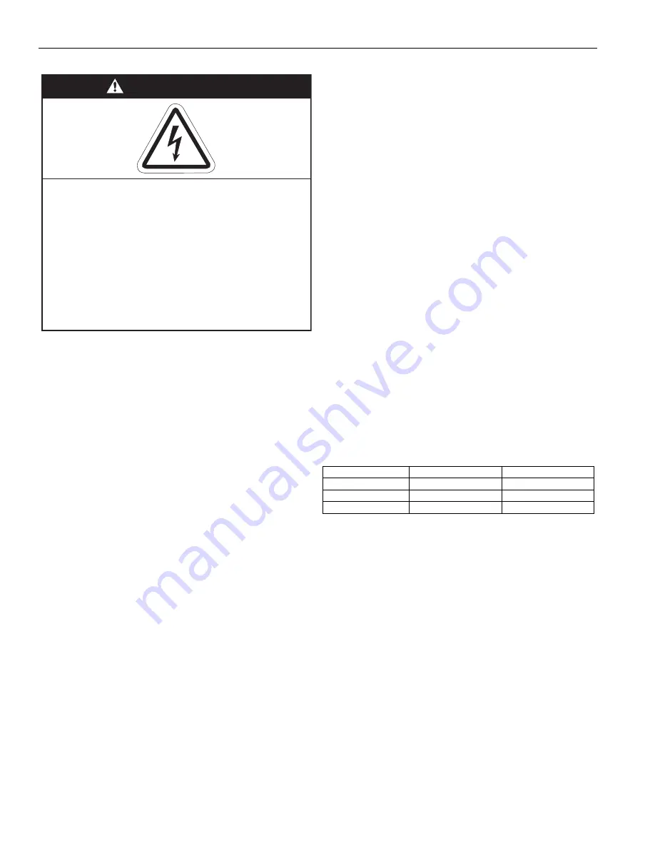
DANGER
Electrical Shock Hazard
Disconnect electric before service.
More than one disconnect switch may be
required to disconnect electric from
equipment.
Equipment must be properly grounded.
Failure to follow these instructions can result
in death or electrical shock.
Volts
Wire Gau
g
e
Max Wire
120
18
150' (45 m)
120
16
250' (75 m)
120
14
350' (106 m)
Summary of Contents for 2005
Page 2: ......
Page 4: ......
Page 8: ......
Page 10: ......
Page 31: ...SECTION 7 ROOF CURB 21 of 147 FIGURE 12 Curb Mounting Air Handler Roof Curb Fastening Detail...
Page 154: ...B SERIES INSTALLATION OPERATION AND SERVICE MANUAL 144 of 147...
Page 158: ......
Page 160: ......
Page 161: ......
Page 162: ......


