4000-S
ERIES
I
NSTALLATION
, O
PERATION
AND
S
ERVICE
M
ANUAL
52 of 154
SECTION 12: INLET HOODS
Inlet hoods are shipped
u
nassembled and m
u
st be assembled prior to installation.
NOTE:
Check to be s
u
re that all req
u
ired components are present. If any are missing, contact Rapid
Engineering LLC or yo
u
r RAPID
®
independent distrib
u
tor.
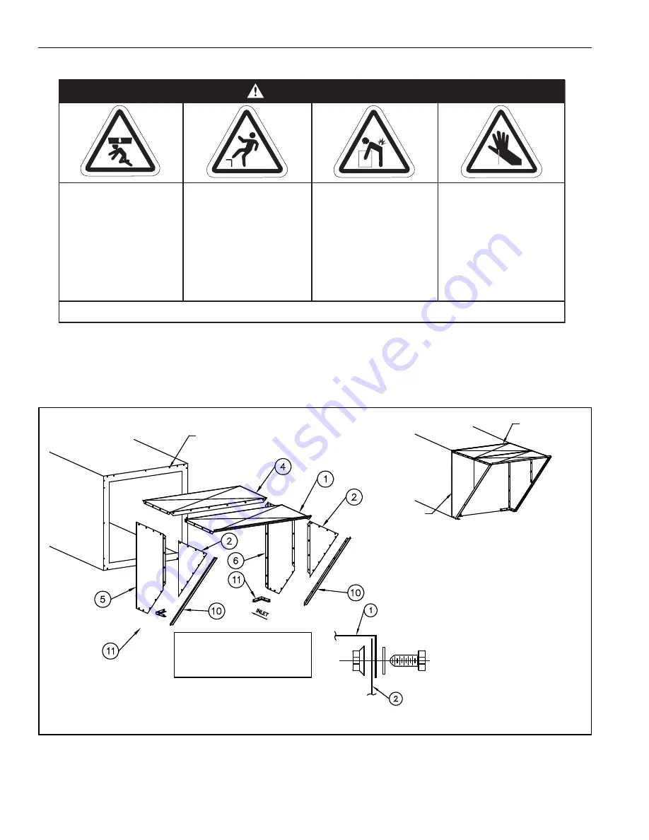
12.1 Inlet Hood Assembly
FIGURE 39: Inlet Hood without Filters (4024-4049)
Crush Hazard
Use proper lifting
equipment and
practices.
Falling Hazard
Use proper safety
equipment and prac-
tices to avoid falling.
Severe Injury Hazard
Use proper lifting
practices and equip-
ment.
Equipment and
accessories are
heavy.
Cut/Pinch Hazard
Wear protective gear
during installation,
operation and
service.
Edges are sharp.
WARNING
Failure to follow these instructions can result in death, injury or property damage.
Roof
Tape
Field Joint
Properly
Caulk
Notes:
(1) Failure to properly caulk the
field joints will allow water
to enter the air handler
(2) All parts mounted to inlet end
to be attached with 3/8" bolt
and flat washers.
(3) All other parts bolted together
with 5/16" bolts, flat washer,
and lock nut.
(4) All dimensions & weights are
subject to change without
notice & should not be used
for construction unless certified.
Typ. Assembly
Nut Inserts
Rapid recommends assembling
inlet hood parts to the air
handler in the following
sequence by item #:
5, 6, 11, 4, 2, 1, 10
Summary of Contents for 4044
Page 2: ......
Page 4: ......
Page 6: ......
Page 8: ......
Page 73: ...SECTION15 VIBRATION ISOLATION 65 of 154 FIGURE 52 Curb Mounted Roof Curb Roof Curb...
Page 109: ...SECTION19 ELECTRICAL 101 of 154...
Page 110: ...4000 SERIES INSTALLATION OPERATION AND SERVICE MANUAL 102 of 154...
Page 111: ...SECTION19 ELECTRICAL 103 of 154...
Page 112: ...4000 SERIES INSTALLATION OPERATION AND SERVICE MANUAL 104 of 154...
Page 113: ...SECTION19 ELECTRICAL 105 of 154...
Page 114: ...4000 SERIES INSTALLATION OPERATION AND SERVICE MANUAL 106 of 154...
Page 115: ...SECTION19 ELECTRICAL 107 of 154...
Page 116: ...4000 SERIES INSTALLATION OPERATION AND SERVICE MANUAL 108 of 154...
Page 117: ...SECTION19 ELECTRICAL 109 of 154...
Page 118: ...4000 SERIES INSTALLATION OPERATION AND SERVICE MANUAL 110 of 154...
Page 119: ...SECTION19 ELECTRICAL 111 of 154...
Page 121: ...SECTION 20 DIRECT FIRED BURNER 113 of 154 FIGURE 71 Midco HMA 2A Burner...
Page 122: ...4000 SERIES INSTALLATION OPERATION AND SERVICE MANUAL 114 of 154...
Page 125: ...SECTION 20 DIRECT FIRED BURNER 117 of 154...
Page 126: ...4000 SERIES INSTALLATION OPERATION AND SERVICE MANUAL 118 of 154...
Page 127: ...SECTION 20 DIRECT FIRED BURNER 119 of 154 20 3 Honeywell UV Flame Detector...
Page 160: ...4000 SERIES INSTALLATION OPERATION AND SERVICE MANUAL 152 of 154...
Page 161: ...SECTION 27 THE RAPID 4000 SERIES WARRANTY 153 of 154...
Page 162: ...4000 SERIES INSTALLATION OPERATION AND SERVICE MANUAL 154 of 154...


