6
Read the user’s manual carefully before use.
This riveter is equipped with our Multi™ nozzle, allowing you to
set Ø3,2 mm - Ø4 mm - Ø4,8 mm rivets with an unique nozzle.
I. Driving tool requirements
1. The tool must be equipped with
adjustable torque setting
Battery-powered drill or screwdriver that allows you to
choose between several torque positions. The torque is set
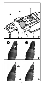
by rotating the torque adjustment collar, behind the chuck (Figure
2.F). The higher the torque is, the more force the screwdriver has.
Note: In some cases, the value in Nm is replaced by setting num-
bers (e.g. 1 to 5) where 1 is the minimum torque value and 5 the
maximum.
2.
Minimum battery power required
with cordless driving tool:
• For aluminium, steel and coppered rivets : 12V
• For stainless steel rivets : 14.4V
3.
Driver mode
(
MUST NOT
be in drill mode nor impact mode)
(Figure 2.G)
4.
Always start with lowest speed (RPM)
To do so, set the button with 2 settings to position 1 (when applica-
ble) which is the slowest speed (Figure 2.H). Then, smoothly pull the
trigger and gradually increase until it works well.
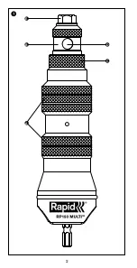
II. Features
A. Grip areas
B. Front tube
C. Locking ring
D. Inspection hole / Plunger tube
E. Nose piece
F. Torque adjustment collar
G. Drill/Driver button
H. Speed button
III. Safety guide
1.
Always wear adequate protective gear
, especially ANSI approved
goggles and thick work gloves (Rubber coated).
2. We recommend to only use rivets sold by Rapid. To choose the
best size according to your material thickness, please refer to the
communication on the rivet packaging.
3. The work piece
MUST BE
secured to avoid possible injury. Unse-
cured objects may rotate with the driving tool.
IV. Operating instructions
1. Ensure that everything is
WELL TIGHTENED
before use and be
careful that this remains as it is
BY CHECKING REGULARLY
.
2. You
MUST HOLD
the riveter fi rmly by the grip areas with thick
gloves when using it. The riveter should not rotate.
3. Operate your driving tool
BACKWARD
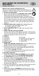
(anti-clockwise) until an
audible sound comes from the riveter. Confi rm from the inspection
hole on the front tube that the plunger tube inside is at its maximum
forward position (Figure 3).
4. Insert the rivet mandrel into the nosepiece hole and make sure there
is no space between the nosepiece and the rivet fl ange
(Figure 4).
5. Lightly pull the trigger in
FORWARD
(clockwise) direction to have
the mandrel slightly gripped by the riveter, to prevent it from falling
out (Figure 5).
MULTI RIVETER FOR SCREWDRIVER :
RP150 MULTI™
Original instructions
Summary of Contents for RP150 MULTI
Page 2: ...2 A B C D E...
Page 3: ...3 H G F...
Page 4: ...4...
Page 30: ...30 12 14 4 3 2 G 4 1 2 H II C D E F G H III 1 ANSI 2 Rapid 3 IV 1 2 3 3 4 4 5 5 6 7 8 V 1...
Page 31: ...31 VI 1 16 1 8 1 3 VII 5001578 3x...
Page 47: ...47 riveter 3 4 4 5 5 6 7 8 V 1 VI 1 16 1 8 1 3mm VII Art No 5001578 3x...


