28
4.3 Control Panel Assembly (accessory)
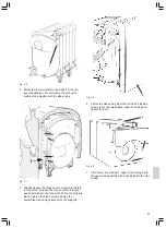
After assembling and aligning the boiler casing the control
panel can be installed.
8 Uncoil capillary tubes and cables and guide them
through the upper boiler casing. Route the burner
cable with seven- and four-pin plugs behind the front
plate up to the burner level.
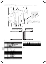
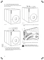
9 Click control panel
1
and cover plate
2
into the boiler
casing.
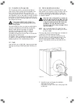
10 Insert the sensor elements 1 into the thermometer
wells 2.
During electrical installation observe the
installation instructions for the control panel.
Fig. 4.10
Fig. 4.12
1
2
Fig. 4.11
Fig. 4.13

