Chapter 3: Installation and Configuration
28
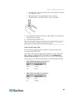
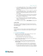
Note: Each button controls the spring of each corresponding
termination point.
3. Fully insert each wire of both third-party detectors/switches into each
termination point.
Plug both wires of a detector/switch into the two termination points
to the left.
Plug both wires of another detector/switch into the two termination
points to the right.
4. Release the tiny rectangular buttons after inserting the wires properly.
5. Verify that these wires are firmly fastened.
Configuring a Contact Closure Sensor
Before using DPX-CC2-TR to detect the contact closure status, water,
smoke or vibration, you must determine the normal state by adjusting its
dip switch, which controls the LED state on the body of DPX-CC2-TR. A
dip switch is associated with a channel.
To adjust the dip switch setting:
1. Place the detectors/switches connected to DPX-CC2-TR to the
position where you want to detect a specific environmental situation.
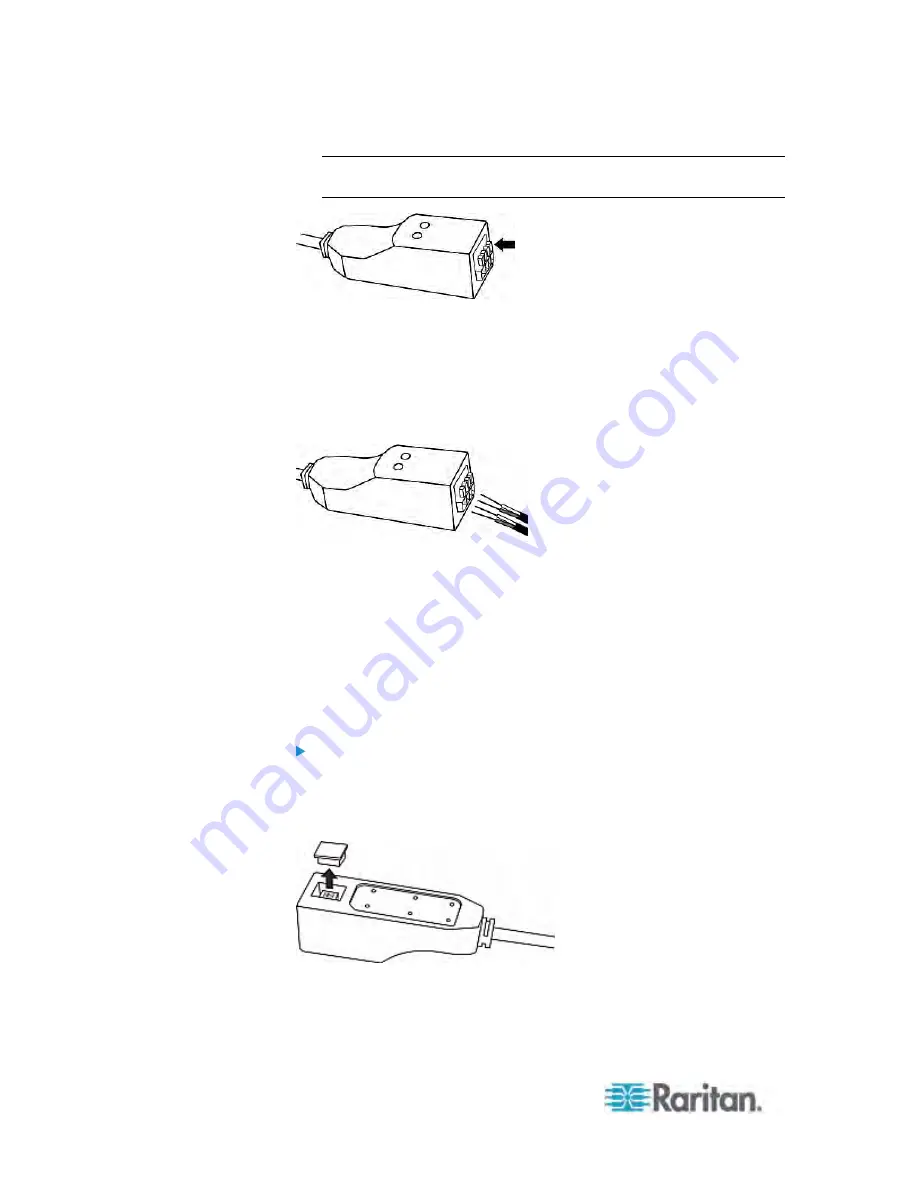
2. Uncover the dip switch on the body of DPX-CC2-TR.
3. To set the Normal state for channel 1, locate the dip switch labeled 1.
4. Use a pointed tip such as a pen to move the slide switch to the end
labeled NO (Normally Open) or NC (Normally Closed).


