background image

15

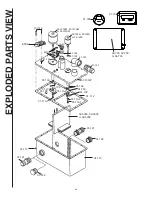
EXPLODED PARTS LIST

Part No.

Description

32-102A** Mixer Motor 2 1/2'' Dia. 12 VDC
33-102A** Mixer Motor 2 1/2'' Dia. 24 VDC
34-102A** Mixer Motor 2 1/2" Dia. 32 VDC
31-121

Hose Fitting (2)

31-120

Discharge Elbow 90°

M30

Electrode Nut 1/4-20 Brass (4)

M31

Electrode #14 Brass flat washer (4)

31-103

Motor Shaft Bushing (2)

31-106

10-32x7/8''RHMS,S/S (4)

31-109

Mixer Impeller

31-110-1

Impeller Bolt, 12-24x5/8'', S/S (2)

31-110-2

Impeller Lock Washer, #12, S/S (2)

31-113-2

Terminal Block Bolt

31-134

Cover Hold Down Screw 10-32 x 1 Hex(16)

31-114

Cover Hold Down Nut, 10-32 (18)

31-115

Treatment Tank

31-122

Intake Plug

32-5000

Electrode Pack 12 VDC

33-5000

Electrode Pack 24 VDC

34-5000

Electrode Pack 32 VDC

31-112

Cover Gasket

31-108

Macerator Set Screw, 8-32x3/16'', S/S

31-107

Macerator Impeller

31-101W

Treatment Cover

31-104C

Crossover Plug

31-105

O-Ring

31-102

Motor Shaft Seal (2)

32-101AW**

Macerator Motor 3'' Dia. 12 VDC

33-101AW**

Macerator Motor 3'' Dia. 24 VDC

34-101AW**

Macerator Motor 3'' Dia. 32 VDC

ETB2

Terminal Block

31-3001

Salt tank unit complete, two gallon (not
shown)

31-3002

Four gallon salt feed tank (not shown)

32-3003

Four gallon salt feed tank w/12 volt
pump  (not shown)

33-3003

Four gallon salt feed tankw/24 volt
pump (not shown)

32-7000

12 V DC Treatment Unit - No Control Unit, System
Status Panel or LCD Display

33-7000

24 V DC Treatment Unit - No Control Unit, System
Status Panel or LCD Display

34-7000

32 V DC Treatment Unit - No Control Unit, System
Status Panel or LCD Display

TREATMENT  UNIT

(  ) Indicates Total pieces required

 CONTROL

Part No.

Description

31-618

Cable for LCD and System Status Panel
(not shown)

31-702

LCD Display

31-705

System Status Panel

32-700

Control Unit 12V

33-700

Control Unit 24V

34-700

Control Unit 32V

WAES01T Wire Harness (not shown)

Summary of Contents for Electro Scan EST12

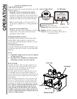
Page 1: ...f any other substance is introduced by accident the electro scan must not be turned on until entire system is flushed out with water electro scan is a U S Coast Guard Certified Type I Marine Sanitatio...

Page 2: ...void warranty How it works Each time the toilet is flushed an equal amount of previ ously treated waste is discharged The electro scan does not pump waste out The flushing action of the toilet moves...

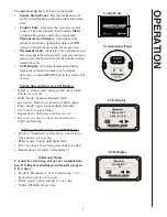
Page 3: ...time screen using and keys when unit is not in cycle Hold mode button until digits flash use and button to set hour in military time Push mode again for next digits minutes Use and to set minutes Rep...

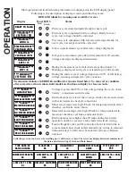
Page 4: ...OVERLD MIX MOTOR OVERLD MIX MOTOR OVERLD ERROR ERROR ERROR ERROR ERROR MaC MOTOR OVERLD MaC MOTOR OVERLD MaC MOTOR OVERLD MaC MOTOR OVERLD MaC MOTOR OVERLD ERROR ERROR ERROR ERROR ERROR ELECTROD OVERL...

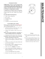
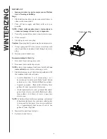
Page 5: ...ctions to ensure no damage is done to any components 3 Turn off power and disconnect wires to electro scan WARNING electro scan must not be activated while muriatic acid solution is in the system 4 In...

Page 6: ...s and turn power on NOTE electro scan treatment tank must be full with sea water salinity water before activating a cycle 3 Flush toilet using one of the following methods to fill the treatment tank w...

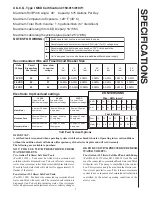
Page 7: ...a 2 2 s p m a 5 3 s p m a 5 3 w a r d p m a 2 2 r o t o M r o t a r e c a M s p m a 5 3 s p m a 0 3 w a r d p m a 0 2 s p m a 5 3 s p m a 0 3 w a r d p m a 6 1 s p m a 5 3 s p m a 0 3 w a r d p m a 9...

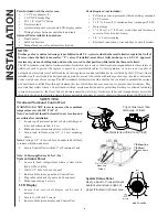
Page 8: ...es Y valves if installed must direct toilet discharge to a U S C G approved treatment system or holding tank and must be secured in that position while inside the three mile limit The EPA standards st...

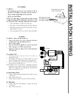
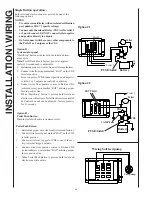
Page 9: ...iring can damage the Circuit Board and void warranty Treatment Unit 1 Determine proper wire size from wire chart on specifications page 2 Run supply wire from source Positive POS to control unit and N...

Page 10: ...let 1 or 2 outputs on control box utilizing 4 Connect wire from positive source to Raritan CDS solenoid relay post marked BAT utilizing proper fuse in positive line 5 When Start Stop button is pressed...

Page 11: ...INTA KE BLUE TOILET CONTROL FROM LST ORANGE POS OFF FLUSH CONTROL PANEL DISCH WHITE ON 1 2 3 NEG BLAC K RARITAN AUX HEAD 2 HEAD 1 SALT FD NEG NEG NEG NEG MAN IN MAN IN EXT TRIG EXT TRIG FUSES HD NEG H...

Page 12: ...12 This page left blank...

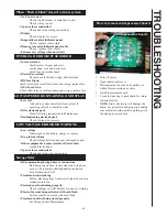
Page 13: ...ry charge or replace Drop in line voltage Check voltage between pos post and negative post Other equipment on same circuit as Electro Scan Isolate Electro Scan Open or loose connections Check and clea...

Page 14: ...5000 or 34 5000 31 112 31 109 31 103 31 106 31 110 2 31 110 1 31 110 2 31 110 1 31 106 31 107 31 108 31 103 31 101W 32 700 33 700 or 34 700 ETB2 31 705 31 702 M30 M31 31 113 2 31 134 32 101AW 33 101AW...

Page 15: ...101W Treatment Cover 31 104C Crossover Plug 31 105 O Ring 31 102 Motor Shaft Seal 2 32 101AW Macerator Motor 3 Dia 12 VDC 33 101AW Macerator Motor 3 Dia 24 VDC 34 101AW Macerator Motor 3 Dia 32 VDC E...

Page 16: ...FOR THIS PROVISION MIGHT ARISE BY IMPLICATION OR OPERATION OF LAW IS HEREBY EXCLUDED AND DISCLAIMED ALL IMPLIED WARRANTIES SUCH AS THOSE OF MERCHANTABILITY AND OF FITNESS FOR A PARTICULAR PURPOSE IF...

Reviews: