background image

Chapter 3: MasterConsole Digital-LED KVM Drawer 
 

16


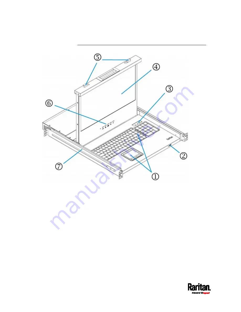
Front View 


Summary of Contents for MCD-LED17 series

Page 1: ...MasterConsole Digital MCD and MCD LED17 Series User Guide Release 1 0 0 Copyright 2017 Raritan Inc MCD 0A v1 0 0 E April 2017 255 20 0007 00...

Page 2: ...y and if not installed and used in accordance with the instructions may cause harmful interference to radio communications Operation of this equipment in a residential environment may cause harmful in...

Page 3: ...erature of the appliances See Specifications on page 73 in online help Ensure sufficient airflow through the rack environment Mount equipment in the rack carefully to avoid uneven mechanical loading C...

Page 4: ...erface Modules 9 MDUTP Cables 10 MCD Rackmount Procedure 10 Step 1 Attach the Cable Support Bar 11 Step 2 Rack Mount the MCD 11 Chapter 3 MasterConsole Digital LED KVM Drawer 13 MCD LED Product Overvi...

Page 5: ...on 43 Resetting to Factory Defaults 44 More Channel Information 44 Active and Inactive Channels 45 Channel Colors 46 Releasing a Channel in the PC Shard Mode 47 Chapter 6 Two Tier System 48 Overview 4...

Page 6: ...de Utility 63 Step 2 Connect the Desired Switch to the Computer Running the Upgrade Utility 63 Step 3 Launch the Upgrade Utility for the Switch 65 Step 2A Launch the Upgrade Utility and Connect MDCIM...

Page 7: ...mation on either product model see MasterConsole Digital KVM Switches on page 5 or MasterConsole Digital LED KVM Drawer on page 13 Important To support audio you must purchase MCD KVM switches instead...

Page 8: ...Chapter 1 Introduction to MasterConsole Digital Series Products 2 MCD LED KVM combination switch and KVM drawer MDCIM DVI...

Page 9: ...Chapter 1 Introduction to MasterConsole Digital Series Products 3 MDCIM HDMI MDCIM DP...

Page 10: ...nvironment The surface for placing and fixing this product should be stable and level or mounted into a suitable cabinet Make sure the place has good ventilation is out of direct sunlight away from so...

Page 11: ...ervers to a MCD switch and you will be able to switch among servers connected to that MCD switch If cascading MCD switches to form a two tier system the number of accessible servers can be expanded up...

Page 12: ...e number of servers is model dependent MCD 108 supports a maximum of 8 servers MCD 116 supports a maximum of 16 servers MCD 216 supports a maximum of 16 servers MCD 232 supports a maximum of 32 server...

Page 13: ...an active channel see Active and Inactive Channels on page 45 Password protection prevents unauthorized access to MCD devices and servers one administrator and 127 user accounts Easy firmware upgrade...

Page 14: ...ctive channels Turn on for active channels The color is white and will turn green when any channel is being accessed Note For the definition of inactive and active channels see Active and Inactive Cha...

Page 15: ...available on all MCD models 3 a b c Refer to a b and c shown above 4 Reset button Power cycles the MCD switch Note that users are forced to log out on reset 5 Firmware upgrade connector Connect a comp...

Page 16: ...us MDUTP cables of different lengths Each MDUTP cable comes with an HD15 VGA connector a USB connector and an analog audio connector Therefore this cable can transmit analog audio in addition to keybo...

Page 17: ...e the rear of the rack fasten the bar to the L shaped holes close to the ears of the rackmount brackets To attach the cable support bar 1 Insert either end of the cable support bar into one of the L s...

Page 18: ...racket with two threaded holes on one side of the MCD 3 Secure the bracket to the MCD with two of the included screws 4 Repeat the same steps for attaching the other bracket 5 Mount the MCD in the rac...

Page 19: ...h an audio capable MDCIM or MDUTP cable is used MCD LED includes the following two models Both models come with a 17 LED LCD display MCD LED17108 MCD LED17116 The adjustable bracket length of either m...

Page 20: ...mprises some or all of the following MCD LED switch MCD Computer Interface Modules MDCIMs and or MDUTP cables Note You CANNOT connect a MCD LED KVM drawer to Raritan s Dominion KX III or KX2 101 V2 be...

Page 21: ...therefore update the channel status Note For the definition of an active channel see Active and Inactive Channels on page 45 Password protection prevents unauthorized access to MCD LED devices and ser...

Page 22: ...Chapter 3 MasterConsole Digital LED KVM Drawer 16 Front View...

Page 23: ...which adjusts the video or OSD settings of the built in LCD display For detailed information see MCD LED Display s OSD Menu on page 55 Note This OSD menu is different from the OSD for channel selectio...

Page 24: ...IMs and MDTUP Cables All MDCIMs and MDUTP cables work with either MCD or MCD LED KVM products MDCIMs See MCD Computer Interface Modules on page 9 MDUTP cables See MDUTP Cables on page 10 MCD LED Rackm...

Page 25: ...Chapter 3 MasterConsole Digital LED KVM Drawer 19 2 Fasten the brackets to the rack rails securely with your own fasteners 3 Slide the MCD LED between the brackets 4 Fasten the MCD LED to the rack...

Page 26: ...ration on page 25 In This Chapter Basic Installation 20 Using the MCD LED 24 Initial OSD Operation 25 Basic Installation Server connection methods are the same for both MCD switches and MCD LED KVM dr...

Page 27: ...UTP cable you purchase is not compatible with the video port on your server the alternative solution is to connect a video converter or adapter to MDCIM or MDUTP Step B Connect the Keyboard Mouse Moni...

Page 28: ...rs Step C Connect Servers 1 Connect one MDCIM or MDUTP cable to the server a Plug the MDCIM or MDUTP s USB connector into one of the server s USB ports b Plug the MDCIM or MDUTP s video connector into...

Page 29: ...MCD switch The distance can be up to 45 meters 147 6 feet MDCIM Use a standard network patch cable Cat5e 6 UTP to connect the MDCIM attached with the server to the MCD channel ports MDUTP cable Simpl...

Page 30: ...the LCD display 4 To fine tune the video quality after accessing a server do either below Press the UP AUTO button on the LCD display Press MENU make sure Auto Adjust has been selected and press MENU...

Page 31: ...me OSD operations Login After turning on the device the login screen displays For initial login use the built in administrator account To log in 1 Type the default user credentials and press Enter Use...

Page 32: ...o change the default password for the security of your MCD system For details refer to User Management on page 35 in the User Guide Accessing a Server After login you can select any channel to view an...

Page 33: ...wn or Page Up 3 Press or to select one of the active channels and press Enter Channels with channel names displayed are active channels The default name is PC See Active and Inactive Channels on page...

Page 34: ...roll Lock Scroll Lock 15 Enter Important If you do not press Enter no channel switching occurs 3 The video of the accessed server displays onscreen Now you can control the server with the keyboard and...

Page 35: ...ferent from those for the MCD LED s LCD display which are described in the chapter titled MCD LED Display s OSD Menu on page 55 In This Chapter OSD Layout 29 Specifying Channel Names 34 User Managemen...

Page 36: ...evice ID The model name of your MCD switch User Port The ID number of your console 01 refers to Console 1 02 refers to Console 2 which is only available on dual user models User Name Password The fiel...

Page 37: ...rs of current page Channel names Available channel names of current page Per default an active channel s name is PC You must customize the channel names See Specifying Channel Names on page 34 The cha...

Page 38: ...ch s model name Your 1st tier MCD s model name 1st tier channel The number of the 1st tier channel where the 2nd tier MCD switch is connected Selected 2nd tier channel The number of the 2nd tier chann...

Page 39: ...channel ID A channel ID on a standalone switch or on the base switch of a two tier system looks similar to the following Note For information on two tier systems see Two Tier System on page 48 Channel...

Page 40: ...hannel name will disappear or be moved to another port if you swap the MDCIM or MDUTP to a different port To change channel names 1 If the OSD is not displayed press the hot key 3 times The default ho...

Page 41: ...user001 through user127 Default passwords are NOT available You CANNOT remove the built in administrator and user accounts but you can change their passwords or rename any user accounts Only the admin...

Page 42: ...is not shown on the current page 5 Press Enter and that user s password change page displays Then follow either procedure below 6 After finishing the user accounts changes press Esc to exit the User C...

Page 43: ...he name can comprise up to 16 characters To keep the user name unchanged simply press Enter without typing any characters 2 In the New Password field type the new password and press Enter A password c...

Page 44: ...tion Menu press F1 The SETUP page displays Note The two settings Oper Mode and Port Timeout are available on dual user models only One user models including MCD LED series do NOT have the two fields 3...

Page 45: ...user loses the server control and the other user if available can gain the server control Scan Mode All or PC ON This determines which servers will be scanned after activating the channel scan functi...

Page 46: ...an adjust the onscreen position of the main OSD or the channel ID Only the administrator can determine the OSD position To adjust the OSD position 1 Log in as the administrator that is admin For detai...

Page 47: ...ns a channel port where a 2nd tier switch is connected it will scan all channels of the 2nd tier switch first before proceeding with the next channels on the base switch Before turning on the scan fun...

Page 48: ...at returns back to normal indicating the scan mode ends For details on channel IDs see Channel ID on page 33 Generic channel ID 2nd tier channel ID Video Adjustment You can adjust the following video...

Page 49: ...You can check the current versions of OSD and USB driver implemented on the MCD to determine whether it is necessary to update your MCD See Firmware Upgrade on page 62 To view the current firmware ver...

Page 50: ...o factory defaults To reset system settings 1 Log out to show the Login screen See Logout on page 28 2 Press Ctrl Shift F10 The following message appears 3 Press Enter to proceed with the factory rese...

Page 51: ...lways powered when plugged into a server that is turned ON but may or may not be powered when the server is turned OFF which depends on the server s design Inactive channels The MCD switch recognizes...

Page 52: ...turns red when the other user is accessing it If the accessed channel is on a 2nd tier switch the tiered channel turns red and you cannot access any channel on that 2nd tier switch In the PC Share mo...

Page 53: ...annel with the other user Depending on the channel access sequence you may or may not be able to control the server If you access the channel earlier than the other user you can control the server and...

Page 54: ...nels 53 Overview To organize a two tier system just connect one or multiple MCD switches to a MCD switch All MCD switches connected to the same MCD switch are the SECOND TIER devices and the FIRST TIE...

Page 55: ...ier switch s Console 1 connector You cannot connect the base switch to its Console 2 connector When a dual user model operates as a 2nd tier switch its Console 2 connector is automatically disabled so...

Page 56: ...onnectors of the 2nd tier switch You CANNOT connect them to Console 2 b Use a standard network patch cable Cat5e 6 UTP to connect the 2nd tier MDCIM to any channel port of the base switch 3 Repeat the...

Page 57: ...Mice Monitors and Audio Devices You must connect one or two sets of keyboards mice and monitors to the base switch For details on connecting keyboards mice monitors and optional audio input devices se...

Page 58: ...Chapter 6 Two Tier System 52 Warning If any 2nd tier switch is a dual user MCD model DO NOT connect a keyboard mouse and monitor to Console 2 because Console 2 is disabled...

Page 59: ...od to access the 2nd tier channels is the OSD s Selection Menu To return to the base switch s channels you also have to operate the Selection Menu To access the 2nd tier channels 1 If the OSD is not d...

Page 60: ...nnel and press Enter 5 The video of the selected channel displays on the screen with its channel ID shown for seconds See Channel ID on page 33 Now you can view or control the server being accessed To...

Page 61: ...e OSD for channel selection and system settings Note The OSD settings described in this chapter are different from those for channel selection and system settings which are described in the chapter ti...

Page 62: ...the video signal output VGA or DVI For details see Selecting the Preferred Video Output on page 61 While the LED OSD is being displayed pressing this button moves down the selection MENU This button h...

Page 63: ...ion An Auto Adjusting message is displayed during the process Luminance Brightness Make the screen image brighter or darker Contrast Adjust the difference between the background black level and foregr...

Page 64: ...ustment is needed only for VGA signals when Auto Tune does not get the optimum video performance and vertical dark bands are visible on the screen Phase Adjust the phase to synchronize the frequency s...

Page 65: ...white cooler User Preset Adjust red green and blue colors respectively OSD H Position Adjust the horizontal position of the LED OSD V Position Adjust the vertical position of the LED OSD OSD Time Set...

Page 66: ...ese and Russian Recall Recall Color Reset all colors to factory defaults Recall All Reset all settings to factory defaults except for the language setting A confirmation message appears after selectin...

Page 67: ...VGA signals on the LCD display You can switch to DVI signals if higher video quality is preferred To switch between VGA or DVI signals 1 Make sure there is no LED OSD shown onscreen 2 Press the DOWN...

Page 68: ...erview MCD and MCD LED share the same firmware upgrade procedure and firmware files In this chapter the name MCD refers to both MCD switches and MCD LED KVM drawers unless otherwise specified Procedur...

Page 69: ...If the downloaded file does not include the release notes document locate the release notes in the same section and click it to download it 6 Read the release notes prior to start the firmware upgrad...

Page 70: ...Chapter 8 Firmware Upgrade 64 MCD switch MCD LED KVM drawer...

Page 71: ...me Description MCD_USB_HOST_XXX usb XXX is the version number This file upgrades the USB functionality of the switch MCD_OSD_XXX osd This file upgrades the OSD functionality of the switch To perform f...

Page 72: ...o select the appropriate MCD OSD file 5 Select the checkbox of the functionality that you want to upgrade To upgrade both functionalities simply click Select All 6 Click Program to start the upgrade T...

Page 73: ...the computer Then repeat steps 6 to 8 until all switches are upgraded Step 2A Launch the Upgrade Utility and Connect MDCIM MDUTP The following procedure applies to MDCIMs and MDUTP cables but NOT to M...

Page 74: ...Chapter 8 Firmware Upgrade 68 To perform firmware upgrade for MDCIM MDUTP 1 Double click the CIM upgrade utility NuvoISP exe The upgrade utility opens...

Page 75: ...le to detect the connected MDCIM or MDUTP a Plug the USB A connector of the MDCIM or MDUTP into the USB port on the computer b Click Connect in the firmware upgrade utility Warning If the sequence of...

Page 76: ...Chapter 8 Firmware Upgrade 70 4 The utility indicates that it detects the connected MDCIM MDUTP by showing the green message Connected...

Page 77: ...Chapter 8 Firmware Upgrade 71 5 Click APROM to select the appropriate MDCIM MDUTP firmware file 6 Click Start to start the firmware upgrade...

Page 78: ...ly a green message PASS is displayed at the bottom 8 If there are more MDCIMs or MDUTP cables to upgrade keep the utility open remove the currently connected MDCIM MDUTP and reconnect a new one to the...

Page 79: ...A ports for keyboard mouse 2 2 Female DVI I ports for video output 1 1 Female 3 5mm audio jack for audio output 1 1 Female Micro USB for firmware upgrade 1 1 Reset button for power cycle 1 1 AC socke...

Page 80: ...1080 60Hz DVI DDC2B Max power input AC100 240V 1 5A DC12V 5 42A Power consumption DC 12V 5 42A 65W Operating temperature 0 to 50 C Storage temperature 20 C to 60 C Humidity 0 80 RH Non condensing Dime...

Page 81: ...output 2 2 Female Micro USB for firmware upgrade 1 1 Reset button for power cycle 1 1 AC socket 1 1 Power switch 1 1 Channel LEDs white but turn green when accessed 16 32 Power LED blue 1 1 Maximum n...

Page 82: ...x A Specifications 76 Items MCD 216 MCD 232 Storage temperature 20 C to 60 C Humidity 0 80 RH Non condensing Dimension L x W x H 440 x 150 x 44 mm Weight g 2009 2276 Safety CE FCC VCCI UL MTBF 300 000...

Page 83: ...for external keyboard mouse 1 1 Female Micro USB for firmware upgrade 1 1 Ground screw 1 1 AC socket 1 1 Power switch 1 1 Push buttons for the LCD display 5 buttons 1 for power and 4 for operating the...

Page 84: ...s 262 144 Brightness cd m2 300 nits Contrast ratio 650 1 MTBF 15 000 Hours Max power input AC100 240V 1 5A DC12V 5 42A Power consumption DC 12V 5 42A 65W Operating temperature 0 to 50 C Storage temper...

Page 85: ...he rear panel to provide a safe electrical path to the ground Note Currently only MCD LED KVM drawers have the ground screw while MCD switches do NOT have it To prevent any potential shock hazard Conn...

Page 86: ...the Internet Connection Connect the MCD switch to any channel port of the Dominion KX II or III A D2CIM VUSB or D2CIM DVUSB is required Dominion KX2 101 V2 Benefit You can access the MCD switch from a...

Page 87: ...f Cat5 Reach DVI LED KVM Console T1700 LED and T1900 LED series Benefit Turn the console of the MCD switch into a KVM drawer which can be put inside the cabinet or rack Connection Connect the MCD swit...

Page 88: ...Products 1 L Language 59 Limitations of the Two Tier System 49 Login 25 30 35 38 40 Login Screen 30 Logout 28 44 Luminance 57 M Management 58 MasterConsole Digital KVM Switches 1 5 13 MasterConsole D...

Page 89: ...Utility 62 63 Step 2 Connect the Desired Switch to the Computer Running the Upgrade Utility 62 63 Rack Mount the MCD 11 Step 2A Launch the Upgrade Utility and Connect MDCIM MDUTP 62 67 Step 3 Launch...

Reviews: