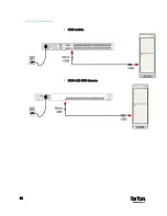
Chapter 6: Two-Tier System
49
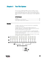
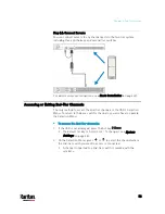
Servers or computers
Cat5 UTP cables
2nd-tier MCD switches
MCD KVM switch (or MCD-LED KVM drawer) as the base switch
Keyboard, mouse, and monitor
Limitations of the Two-Tier System
The two-tier system has several limitations.
There is only one path (Cat5e/6 UTP cable) between the base switch
and each 2nd-tier switch. When a user from the base switch is
accessing any channel of a 2nd-tier switch, there are no other paths
left for the other user from the base switch to access the same
2nd-tier switch's channels.
When using a dual-user model as the 2nd-tier switch, the base
switch must be connected to this 2nd-tier switch's 'Console 1'
connector. You cannot connect the base switch to its 'Console 2'
connector.
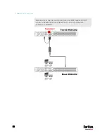
When a dual-user model operates as a 2nd-tier switch, its 'Console
2' connector is automatically disabled so DO NOT connect a local
keyboard/mouse/monitor to its 'Console 2'.
Establishing a Two-Tier System
Major steps include:
STEP (a): Connect the 2nd-tier switch(es) to the base switch
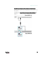
STEP (b): Connect the keyboard, mouse, monitor and audio devices
to the base switch
STEP (c): Connect servers to the two-tier system
Step (a): Connect 2nd-Tier Switches to the Base Switch
You can mix identical or different MCD models in a two-tier system. For
example, you may connect a MCD-116 switch to a MCD-232 base switch.
To cascade MCD switches:
1.
Turn OFF all MCD switches, including the base switch.
2.
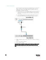
Connect the 2nd-tier MCD switch to the base switch via one
MDCIM-DVI.


