Chapter 6: Using the Web Interface
180
Yellow- or Red-Highlighted Sensors
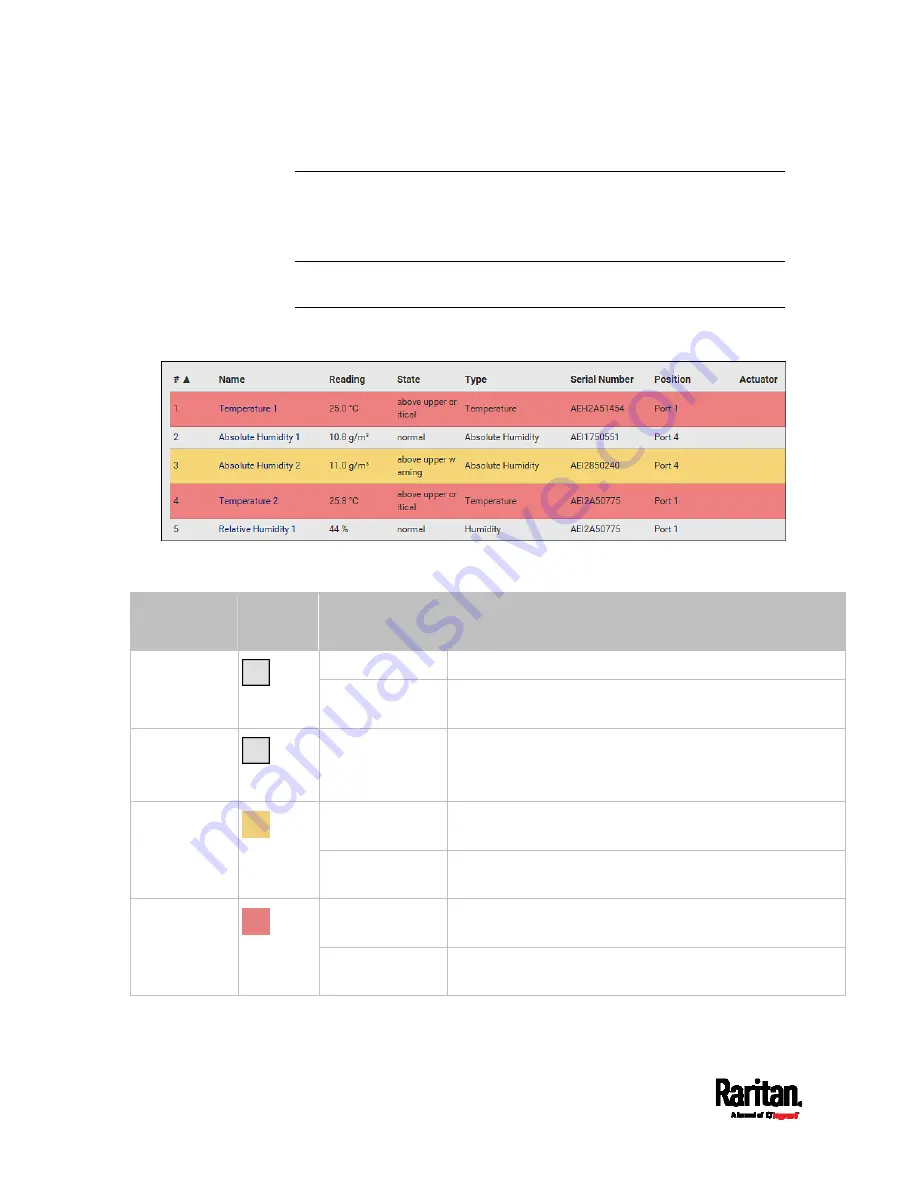
The PX3 highlights those sensors that enter the abnormal state with a
yellow or red color. Note that numeric sensors can change colors only
after you have enabled their thresholds.
Tip: When an actuator is turned ON, it is also highlighted in red for
drawing attention.
For concepts of thresholds, deassertion hysteresis and assertion timeout,
see
Sensor Threshold Settings
(on page 675).
In the following table, "R" represents any numeric sensor's reading. The
symbol <= means "smaller than" or "equal to."
Sensor status Color
States shown in
the interface
Description
unavailable
Sensor state or readings cannot be detected.
Unknown
unmanaged
Sensors are not being managed. See
Managed vs
Unmanaged Sensors/Actuators
(on page 181).
Normal
normal
Numeric or state sensors are within the normal range.
-- OR --
No thresholds have been enabled for numeric sensors.
above upper
warning
Upper Warning threshold < "R" <= Upper Critical
threshold
Warning
below lower
warning
Lower Critical threshold <= "R" < Lower Warning
threshold
above upper
critical
Upper Critical threshold < "R"
Critical
below lower
critical
"R" < Lower Critical threshold
Summary of Contents for PX3-1000 series
Page 5: ......
Page 92: ...Chapter 4 Connecting External Equipment Optional 70...
Page 668: ...Appendix J RADIUS Configuration Illustration 646 Note If your PX3 uses PAP then select PAP...
Page 673: ...Appendix J RADIUS Configuration Illustration 651 14 The new attribute is added Click OK...
Page 674: ...Appendix J RADIUS Configuration Illustration 652 15 Click Next to continue...


