Appendix F: PX3 Phase I LCD Display
560
Inlet Information
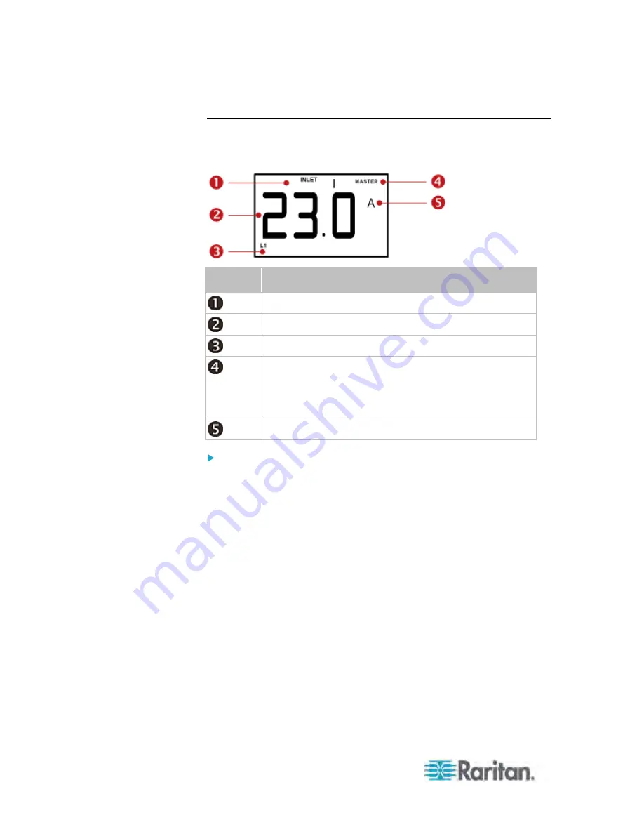
The Inlet mode is displayed as "INLET" on the LCD display. Below
illustrates the inlet information shown on the LCD display.
Section
Example information
The selected target is INLET 1.
This inlet's L1 current reading is 23 amps.
The selected inlet line is L1.
The word "MASTER" indicates the PX is the master
device in a USB-cascading configuration. See
Cascading the PX via USB
(on page 28).
For a standalone PX, this word is NOT displayed.
The measurement unit is A (ampere).
To display an inlet's information:
1. Press the MODE button until the term "INLET" is displayed.
2. On a multi-inlet model, press the Up or Down button until the desired
inlet's number is displayed at the top.
3. If your PX is a 3-phase model, the selected inlet line is indicated
below the reading. Press the Up or Down button until the desired
inlet line's number (L1, L2, L3, L1-L2, L2-L3 or L3-L1) is shown.
4. Press the FUNC button to switch between voltage, active power and
current readings of the selected target.
A is displayed for the current reading. A means Amp.
V is displayed for the voltage reading. V means Volt.
W is displayed for the power reading. W means Watt.
If the word "ALARM" appears below the reading, it means the
currently displayed reading already reaches or crosses the upper or
lower thresholds.
Summary of Contents for PX3-4000 series
Page 5: ......
Page 627: ...Appendix I RADIUS Configuration Illustration 606 Note If your PX uses PAP then select PAP...
Page 632: ...Appendix I RADIUS Configuration Illustration 611 14 The new attribute is added Click OK...
Page 633: ...Appendix I RADIUS Configuration Illustration 612 15 Click Next to continue...
Page 648: ...Appendix J Integration 627 3 Click OK...
Page 661: ...Appendix J Integration 640 2 Launch dcTrack to import the spreadsheet file...


