Chapter 5: Using the PDU
61
Port
Used for...
*SENSOR
Connection to Raritan's environmental sensor packages.
A sensor hub is required if you want to connect more than one DPX sensor
package.
ETHERNET
Connecting the PX device to your company's network:
Connect a standard Cat5e/6 UTP cable to this port and connect the other
end to your network. This connection is necessary to administer or access
the PX device remotely using the web interface.
There are two small LEDs adjacent to the port:
Green indicates a physical link and activity.
Yellow indicates communications at 10/100 BaseT speeds.
For a USB-cascading configuration in the bridging mode, the wired network
connection is a must for the
master
PX. See
Cascading the PX via USB
(on page 28) for details.
Note: Connection to this port is not required if connection to a wireless
network is preferred.
* The SENSOR port on a PX3 PDU is RJ-45.
Dot-Matrix LCD Display
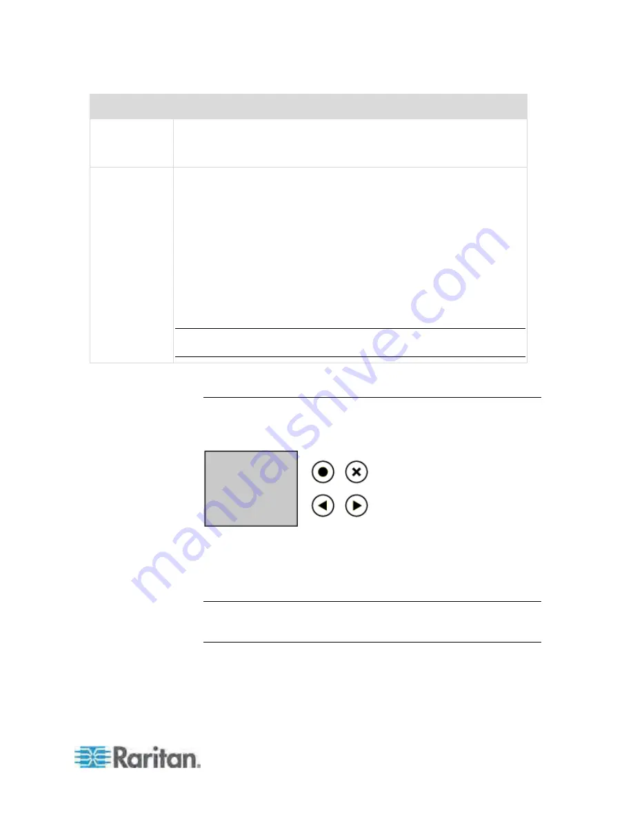
The following diagram shows the dot-matrix LCD display panel on a Zero
U PX3
Phase II
model.
You can use the LCD display to view the PX information and even switch
an outlet. It consists of:
A dot-matrix LCD display
Four control buttons
Note: All dot-matrix LCD display diagrams illustrated in the online help
are for Zero U models. Your dot-matrix LCD display may look slightly
different if it is on a 1U or 2U model.
Summary of Contents for PX3-4000 series
Page 5: ......
Page 627: ...Appendix I RADIUS Configuration Illustration 606 Note If your PX uses PAP then select PAP...
Page 632: ...Appendix I RADIUS Configuration Illustration 611 14 The new attribute is added Click OK...
Page 633: ...Appendix I RADIUS Configuration Illustration 612 15 Click Next to continue...
Page 648: ...Appendix J Integration 627 3 Click OK...
Page 661: ...Appendix J Integration 640 2 Launch dcTrack to import the spreadsheet file...


