Chapter 6: Using the Web Interface
119
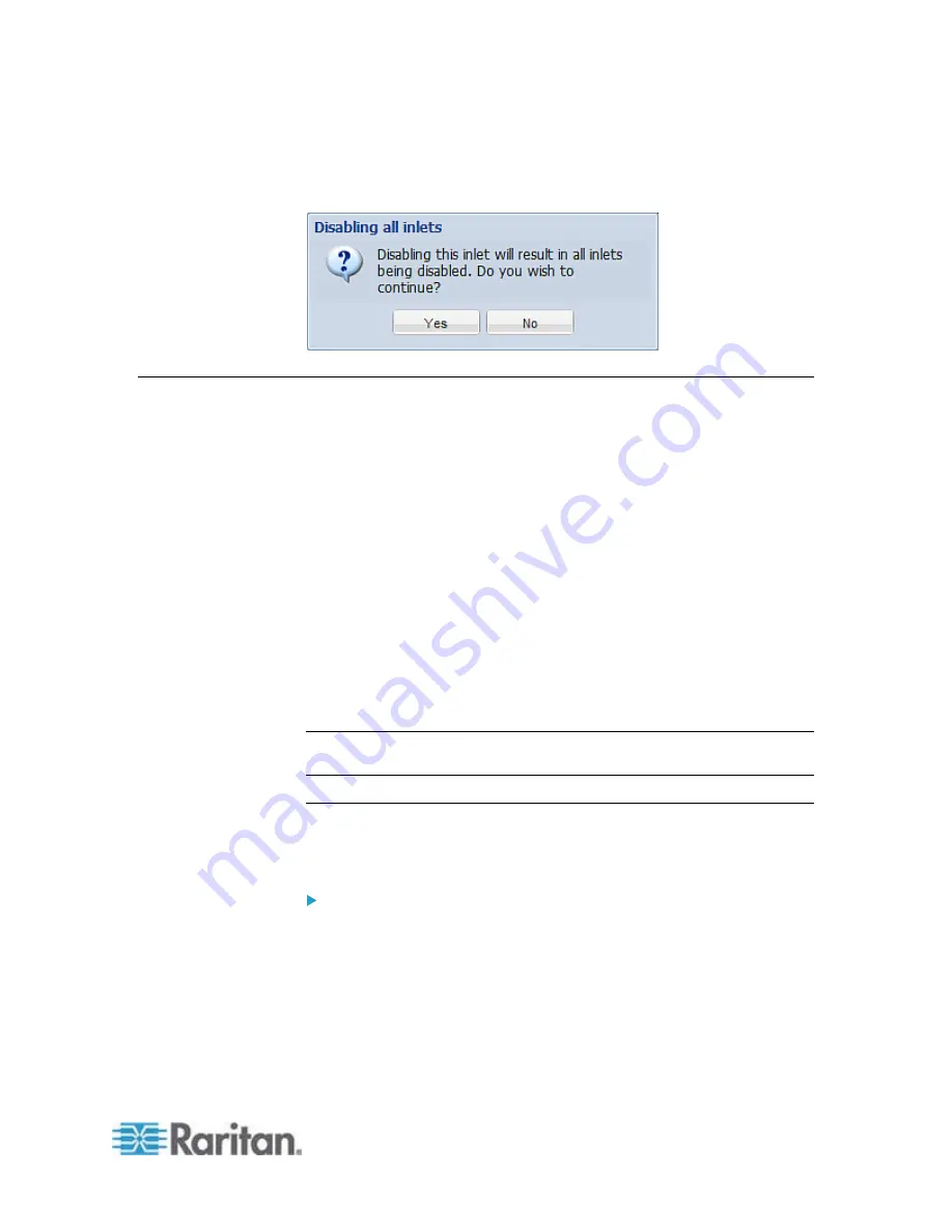
6. If disabling an inlet will result in all inlets being disabled, a
confirmation dialog appears, indicating that all inlets will be disabled.
Then click Yes to confirm this operation or No to abort it.
Setting Power Thresholds
Setting and enabling the thresholds causes the PXE to generate alert
notifications when it detects that any component's power state crosses
the thresholds. See
The Yellow- or Red-Highlighted Sensors
(on page
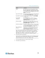
There are four thresholds for each sensor: Lower Critical, Lower Warning,
Upper Warning and Upper Critical.
Upper and Lower Warning thresholds indicate the sensor reading
enters the warning level.
Upper and Lower Critical thresholds indicate the sensor reading
enters the critical level.
To avoid generating a large amount of alert events, you can set the
assertion timeout and deassertion hysteresis.
For detailed information, see
Sensor Threshold Settings
(on page
Note: After setting the thresholds, remember to configure event rules.
See
Event Rules and Actions
(on page 121).
Setting Inlet Thresholds
You can set the inlet thresholds so that the alerts are generated when
the inlet current and/or voltage crosses the thresholds.
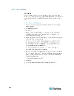
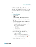
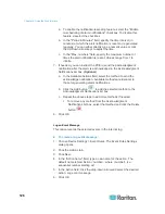
To set the inlet thresholds:
1. Click Inlet I1 in the PX Explorer pane, and the Inlet I1 page opens in
the right pane.
2. Click Setup. The Inlet I1 Setup dialog appears.
3. In the Threshold Configuration table, click the sensor whose
thresholds you want to configure.
4. Click Edit or double-click the desired sensor. A threshold setup
dialog appears.
Summary of Contents for PXE
Page 16: ......
Page 339: ...Appendix A Specifications 323 RS 485 Pin signal definition al 4 5 6 D bi direction al Data 7 8...
Page 380: ...Index 364 Z Zero U Products 1...
Page 381: ......


