Chapter 6: Using the Web Interface
120
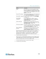
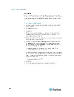
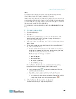
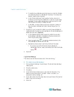
5. Configure the Lower Critical, Lower Warning, Upper Warning and
Upper Critical thresholds respectively.
To enable any threshold, select the corresponding checkbox. To
disable a threshold, deselect the checkbox.
After any threshold is enabled, type an appropriate numeric value
in the accompanying text box.
6. To set the deassertion hysteresis, type a numeric value in the
Deassertion Hysteresis field. See
"To De-assert" and Deassertion
Hysteresis
(on page 354).
7. To set the assertion timeout, type a numeric value in the Assertion
Timeout (samples) field. See
"To Assert" and Assertion Timeout
(on page 352).
8. Click OK in the threshold setup dialog to retain the changes.
9. To set the thresholds for other sensors, repeat Steps 4 to 8.
10. Click OK.
Important: The final step is required or the threshold changes are not
saved.
Summary of Contents for PXE
Page 16: ......
Page 339: ...Appendix A Specifications 323 RS 485 Pin signal definition al 4 5 6 D bi direction al Data 7 8...
Page 380: ...Index 364 Z Zero U Products 1...
Page 381: ......


