Chapter 5: Using the PDU
29
LED Display
The LED display is located on the side where outlets are available.
These diagrams show the LED display on different types of PDUs. Note
that the LED display might slightly vary according to the PDU you
purchased.
The LED display consists of:
A row displaying three digits
A row displaying two digits
Up and Down buttons
Five LEDs for measurement units
Note: When a PXE device powers up, it proceeds with the power-on self
test and software loading for a few moments. When the software has
completed loading, the LED display illuminates.
Three-Digit Row
The three-digit row shows the readings for the selected component.
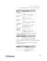
Values that may appear include:
Active power or unbalanced load of the inlet
Current, voltage, or active power of the selected line
Note: L1 voltage refers to the L1-L2 or L1-N voltage, L2 voltage
refers to the L2-L3 or L2-N voltage, and L3 voltage refers to the
L3-L1 or L3-N voltage.
The text “FuP,” which indicates that the
F
irmware
uP
grade is being
performed
Summary of Contents for PXE
Page 16: ......
Page 339: ...Appendix A Specifications 323 RS 485 Pin signal definition al 4 5 6 D bi direction al Data 7 8...
Page 380: ...Index 364 Z Zero U Products 1...
Page 381: ......


