background image


U.S./Canada/Latin America  

Monday - Friday  
8 a.m. - 6 p.m. ET  
Phone: 800-724-8090 or 732-764-8886 
For CommandCenter NOC: Press 6, then Press 1 
For CommandCenter Secure Gateway: Press 6, then Press 2 
Fax: 732-764-8887 
Email for CommandCenter NOC: tech-ccnoc@raritan.com 
Email for all other products: tech@raritan.com 


China 

Beijing  

Monday - Friday  
9 a.m. - 6 p.m. local time  
Phone: +86-10-88091890 

Shanghai 

Monday - Friday  
9 a.m. - 6 p.m. local time  
Phone: +86-21-5425-2499  

GuangZhou 

Monday - Friday  
9 a.m. - 6 p.m. local time  
Phone: +86-20-8755-5561  


India  

Monday - Friday  
9 a.m. - 6 p.m. local time 
Phone: +91-124-410-7881  


Japan  

Monday - Friday  
9:30 a.m. - 5:30 p.m. local time  
Phone: +81-3-3523-5991 
Email: support.japan@raritan.com 


Europe  

Europe 

Monday - Friday 
8:30 a.m. - 5 p.m. GMT+1 CET  
Phone: +31-10-2844040  
Email: tech.europe@raritan.com 

United Kingdom  

Monday - Friday  
8:30 a.m. to 5 p.m. GMT  
Phone +44(0)20-7090-1390  

France  

Monday - Friday  
8:30 a.m. - 5 p.m. GMT+1 CET  
Phone: +33-1-47-56-20-39 

Germany  

Monday - Friday  
8:30 a.m. - 5:30 p.m. GMT+1 CET  
Phone:  +49-20-17-47-98-0 
Email: rg-support@raritan.com  


Melbourne, Australia 

Monday - Friday 
9:00 a.m. - 6 p.m. local time 
Phone: +61-3-9866-6887  


Taiwan  

Monday - Friday  
9 a.m. - 6 p.m. GMT -5 Standard -4 Daylight  
Phone: +886-2-8919-1333  
Email: support.apac@raritan.com  


Summary of Contents for TMCAT17 series

Page 1: ...Copyright 2013 Raritan Inc TMCAT 0D v1 0 E March 2013 255 37 0121 00 TMCAT17 Series User Guide Release 1 0...

Page 2: ...y and if not installed and used in accordance with the instructions may cause harmful interference to radio communications Operation of this equipment in a residential environment may cause harmful in...

Page 3: ...See Specifications Ensure sufficient airflow through the rack environment Mount equipment in the rack carefully to avoid uneven mechanical loading Connect equipment to the supply circuit carefully to...

Page 4: ...rams 6 TMCAT17 Switch 7 MCCAT User Station 8 Chapter 2 Quick Start 10 Before Installation 10 Rackmount Installation 11 Rackmount Kit 11 Rack Mounting the TMCAT17 Device 12 Installing a Basic System 14...

Page 5: ...em Settings 42 Assigning or Modifying Channel Names 43 Changing the Scan Rate 44 Renaming the TMCAT17 Switch 44 Changing Passwords 45 Changing the Hot Key 46 Changing the Operation Mode 47 Setting Up...

Page 6: ...Upgrade Utility 69 STEP C Launch the Upgrade Utility 70 Appendix A Specifications 73 TMCAT17 Specifications 73 Supported Video Resolutions 74 Resolutions for the Built in LCD Display 74 Resolutions f...

Page 7: ...fy the Type of the Second Tier Device on the OSD 89 STEP D Connect Computers to the TMCAT17 System 90 One User MCCAT Switches 90 How to Connect MCCAT18 116 Switches to the Base Switch 91 Setting Up th...

Page 8: ...ers through standard Category 5 Cat5 unshielded twisted pair UTP cables If you connect Raritan s MasterConsole CAT MCCAT KVM switches to the TMCAT17 switch to form a two tier system the number of comp...

Page 9: ...d a USB connector PS 2 type MCIM PS2 comes with an HD15 VGA connector a PS 2 keyboard connector and a PS 2 mouse connector MCUTP Cable One MCUTP cable is a combination of Computer Interface Module CIM...

Page 10: ...3 feet MCUTP60 PS2 6 meters 20 feet Sun USB type This type comes with an HD15 VGA connector a Sun USB connector and an RJ 45 connector Model Cable length MCUTP06 SUSB 0 6 meter 2 feet MCUTP20 SUSB 2 m...

Page 11: ...Chapter 1 Introduction 4 MCCAT UST Front and Rear View MCUTP20 PS2 Cable MCUTP20 USB or MCUTP20 SUSB Cable...

Page 12: ...nnect with computers via standard Cat5 UTP cables Feature simple system control and management with the OSD interface With the keep alive technology you can add remove and hot swap components without...

Page 13: ...the TMCAT17 switch and MCCAT user station TMCAT17 Switch TMCAT17 switch x 1 Power cord x 1 Rackmount kit x 1 including brackets and associated screws Mounting depth adjustable from 560 to 900 mm Quic...

Page 14: ...when the brackets are inserted into the mounting brackets installed in the rack LCD power switch and LED The LCD power switch toggles the LCD display s power on or off When on the adjacent LED is lit...

Page 15: ...ory defaults MCCAT User Station One MCCAT user station can connect a set of keyboard mouse and monitor to any of these devices A compatible KVM switch including MCCAT28 MCCAT216 TMCAT1728 or TMCAT1721...

Page 16: ...PS 2 keyboard port Connects a PS 2 keyboard PS 2 mouse port Connects a PS 2 mouse Power jack Connects a power adapter Warning Do NOT connect both PS 2 and USB keyboards or both PS 2 and USB mice simul...

Page 17: ...a suitable environment The surface for placing and fixing the TMCAT17 should be stable and level or mounted into a suitable cabinet Make sure the place has good ventilation is out of direct sunlight a...

Page 18: ...Chapter 2 Quick Start 11 Rackmount Installation Rackmount Kit Component list Mounting brackets M6 cage nuts M6 washers M6 screws...

Page 19: ...ts have been inserted into the holes of vertical rails where you intend to mount TMCAT17 To rack mount the device Adjust the mounting brackets to fit the depth of your rack Attach them to vertical rai...

Page 20: ...AT17 to make the support brackets slide into the slots of mounting brackets Continue pushing TMCAT17 until the mounting ears contact vertical rails Secure both mounting ears to vertical rails using M6...

Page 21: ...Use MCIM for computers running Windows 98 Note If the computer is a Sun server you must prepare the Sun USB MCUTP cable or DCIM USB G2 instead of MCIM Connecting the Equipment 1 Turn OFF all devices...

Page 22: ...UTP cable a Plug the MCIM or MCUTP s PS 2 mouse connector into the computer s PS 2 mouse port b Plug the MCIM or MCUTP s PS 2 keyboard connector into the computer s PS 2 keyboard port c Plug the MCIM...

Page 23: ...e VGA port on the Sun server Note See Supporting Sun Servers on page 39 in the User Guide for more information 3 Connect the computer to the TMCAT17 switch If using the MCIM a Plug one end of a Cat5 U...

Page 24: ...TMCAT17 switch is compatible with the Paragon II enhanced user station P2 EUST see P2 EUST User Station on page 83 If you have P2 EUST you can connect it instead of the MCCAT user station to the TMCA...

Page 25: ...both PS 2 and USB keyboards or both PS 2 and USB mice simultaneously If you do so only the USB keyboard and or mouse work properly 2 Connect the VGA monitor to the user station 3 Connect the user sta...

Page 26: ...nto the appropriate power outlet 5 Turn on the connected monitor After finishing the installation and turning on all devices you can use the keyboard mouse and monitor connected with the user station...

Page 27: ...when it is installed in a rack Note The diagrams are for illustration and may not look exactly the same as the LCD KVM switch you purchased or the rack in your workplace To open the device 1 Push the...

Page 28: ...settings To access any computer you may log in with any user account To configure the system settings on the Administration Menu you must log in with the administrator account Note XXX shown in the di...

Page 29: ...The password is case sensitive 3 The Selection Menu appears indicating your login is successful Important It is strongly recommended to change the default password for the security of your TMCAT17 sy...

Page 30: ...n in the No column for that channel to quickly highlight it 3 Press Enter The Selection Menu disappears The video of the accessed computer appears on the screen You can control the computer with the k...

Page 31: ...e OSD on the screen press the hot key twice QUICKLY to activate it The default hot key is Scroll Lock 2 Press F9 The Login box appears indicating that you have successfully logged out Closing TMCAT17...

Page 32: ...assembly of the LCD panel and keyboard tray back into the rack until you hear the click sound of latches Note If the assembly is stuck and cannot be pushed back then push the black arrows on both sid...

Page 33: ...tory default is the model name You can customize this name See Renaming the TMCAT17 Switch on page 44 for more information User Port Current input output devices via which you access the TMCAT17 switc...

Page 34: ...settings of the current menu or submenu Message bar The location that displays messages or prompts relevant with current OSD screen Current hot key The hot key that activates the OSD The default is Sc...

Page 35: ...specified if any Channel selection indicator If you are accessing any channel the red arrow appears on the OSD to indicate the channel you are accessing Ch ID The channel port number If sorting the S...

Page 36: ...tions of Highlight Colors The highlight bar can change its colors to indicate different statuses when you are changing settings on specific menus or submenus 1 The highlight color is yellow in the beg...

Page 37: ...varies based on the power status of the connected CIM or MCUTP cable This section explains the definition of active and inactive channels Active Channels The TMCAT17 switch recognizes a channel as bei...

Page 38: ...s table indicates channel statuses and corresponding channel colors Color Channel status Black This is an inactive channel Green This is an active channel that you can access In the Private mode activ...

Page 39: ...42 To switch between pages Key Function Page Up Switches to the previous page Page Down Switches to the next page Home Switches to the first page End Switches to the last page To select fields or cha...

Page 40: ...stem Key Function Esc Exits from the current menu or submenu F9 Logs you out of the TMCAT17 system Others Key Function F6 Toggles the Scan function on or off F7 Toggles the Skip function on or off S S...

Page 41: ...ase switch applies to the base switch alone instead of the whole system For programming instructions see STEP A Programme an MCCAT Switch as a Second Tier Device on page 87 Always perform the operatio...

Page 42: ...the channel sorting Press F12 when the Selection Menu is displayed The Selection Menu switches from the current sorting to the other sorting Sorting by channel number Sorting by channel name Tip When...

Page 43: ...ess F6 The Scan status at the bottom of the OSD turns yellow 3 Press Esc to quit the OSD The system displays the video of each channel one by one on the screen When a channel is being scanned its chan...

Page 44: ...cess the same channel simultaneously PC Share mode functions in one of these scenarios The administrator has turned on the PC Share mode see Changing the Operation Mode on page 47 You are accessing th...

Page 45: ...ves the mouse gains the control of the computer Note It is normal that initial keyboard or mouse inputs are not processed by the computer when the computer control is being shifted to one of the users...

Page 46: ...ctor into one of available USB ports on the Sun server Plug the CIM s video connector into the VGA port on the Sun server 3 Connect the Sun server to one of the channel ports on the TMCAT17 switch via...

Page 47: ...l on the keypad Volume Ctrl Alt the plus symbol on the keypad Volume Ctrl Alt the minus symbol on the keypad Stop Pause Break Refreshing Channel Statuses The TMCAT17 system does not automatically upda...

Page 48: ...Chapter 4 Advanced Operation 41 If few channels are impacted you can access impacted channels one by one to update their channel statuses See Accessing a Computer or Channel on page 23...

Page 49: ...T17 base switch applies to the base switch alone instead of the whole system For programming instructions see STEP A Programme an MCCAT Switch as a Second Tier Device on page 87 Always perform the ope...

Page 50: ...nter The Channel Configuration submenu appears 4 If you do not find the channel on the current page press Page Down or Page Up to go to the next or previous page 5 Press or to highlight the channel na...

Page 51: ...o select the field in the Scn column and press Enter The highlight color turns green 7 Press any arrow key to adjust the numeric value by 1 or type two numeric digits Then press Enter The highlight co...

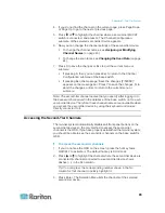
Page 52: ...nel Names on page 43 Changing Passwords It is strongly recommended to change the default password for the security of your TMCAT17 system The default password for the administrator account Admin is ra...

Page 53: ...etting 1 If you do not see the OSD on the screen press the hot key twice QUICKLY to activate it The default hot key is Scroll Lock 2 Press F5 The Administration Menu appears 3 Select the first submenu...

Page 54: ...inistration Menu appears 3 Select the first submenu System Configuration To select the submenu either press 1 or press or to highlight it and then press Enter 4 Press Tab or Shift Tab to highlight the...

Page 55: ...field and press Enter The highlight color turns green 5 Press any arrow key to select the option On and press Enter The highlight color turns yellow 6 Change the timing setting if necessary a Press T...

Page 56: ...to highlight the Logoff Timeout field and press Enter The highlight color turns green 5 Press any arrow key to select the option On and press Enter The highlight color turns yellow 6 Change the timin...

Page 57: ...hen press Enter 4 Press Tab or Shift Tab to highlight the Login Blank field and press Enter The highlight color turns green 5 Press any arrow key to select the option On and press Enter The highlight...

Page 58: ...2 Press F5 The Administration Menu appears 3 Select the second submenu User Configuration To select the submenu either press 2 or press or to highlight it and then press Enter The User Configuration s...

Page 59: ...To assign any password see Changing Passwords on page 45 To change the user name see Renaming User Accounts on page 51 Deleting User Accounts You can remove obsolete user accounts when necessary To d...

Page 60: ...n To turn on the ID display function and adjust the display timing 1 If you do not see the OSD on the screen press the hot key twice QUICKLY to activate it The default hot key is Scroll Lock 2 Press F...

Page 61: ...bort the changes or Esc to return to the current menu or submenu Adjusting the ID Display Position To adjust the channel ID position 1 If you do not see the OSD on the screen press the hot key twice Q...

Page 62: ...nfirm the new position The highlight color turns yellow 7 Press S to save the changes or Esc to quit the current menu or submenu If pressing Esc the message Save the changes Y N ESC appears on the mes...

Page 63: ...set 5 When you hear the beep sound and see the login box displayed on the screen the system reset is complete In a two tier system reset the base switch only Do not reset the second tier devices unles...

Page 64: ...e LCD display and navigate through the LCD s OSD interface Button Function Turn on off the LCD display Adjacent LED turns blue when turned on Adjacent LED is not lit when turned off Two functions Acti...

Page 65: ...e LCD version and the resolution and refresh rate applied to current video image Submenu section The left column shows the OSD submenus Only three submenus are available Image Geometry and Misc Settin...

Page 66: ...of the screen image Contrast Adjust the difference between the image background black level and the foreground white level Color Temp The screen color is not user configurable always at 9300K Red Adj...

Page 67: ...reset function Language Select the language in which the LCD s OSD interface is displayed OSD Position Determine the position of the LCD OSD on the screen Display Mode Adjust the LCD display s video...

Page 68: ...other submenus repeat Steps 2 to 6 8 Press to quit the LCD OSD menu Auto Adjusting Display Settings Instead of customizing the LCD display settings manually you can have the LCD automatically configu...

Page 69: ...lect the Reset field 4 Press or to select the option Yes and then press to confirm Important You must press in this step or the reset function is not performed 5 Press twice to quit the LCD OSD menu I...

Page 70: ...unction is not applicable to USB or PS 2 MCIM and MCUTP cable In This Chapter Changing Keyboard Layout Settings 63 Keyboard Layout Codes 65 Changing Keyboard Layout Settings When you connect a Sun USB...

Page 71: ...ar to the following appears in the text editor A Frequently used keyboard layout codes B Current keyboard layout is US English code 33 4 Press the appropriate keyboard layout code and then the last li...

Page 72: ...keyboard setting mode displays only frequently used keyboard layout codes on the screen For other layout codes see the table Language Layout code Language Layout code Arabic 01 Netherlands 18 Belgian...

Page 73: ...or MCUTP cable see Connecting the Equipment on page 14 2 Ensure that the keyboard mouse and monitor remain connected to the MCCAT user station see Connecting a User Station Optional on page 17 3 Conn...

Page 74: ...ing the MCUTP cable Plug the RJ 45 connector of the cable into the Cat5 Port of the user station Note If any abnormal video issues occur power cycle the MCCAT user station by unplugging and re pluggin...

Page 75: ...website http www raritan com 2 Click Support Firmware and Documentation 3 Locate the product name on the left pane and click it 4 Click the appropriate version or model on the right pane 5 Click Firm...

Page 76: ...CAT17 switch or MCCAT user station to the computer where the upgrade utility is installed Note If you don t have the cable contact Raritan Technical Support for assistance 1 Plug one end of the serial...

Page 77: ...ble click the upgrade utility ParagonUpdate_xxx exe where xxx represents the version number The Paragon Update utility opens 2 If the device that you want to upgrade is already listed in the dialog go...

Page 78: ...Select the checkbox next to the device that you want to upgrade 4 Click Load Hex File The Open dialog appears 5 Navigate to where the appropriate firmware file hex is stored select it and click Open...

Page 79: ...o matter the connected KVM switch is MCCAT or TMCAT17 series 7 Click Raritan MasterConsole to perform the upgrade 8 Click Yes when this message appears 9 A progress indicator at the bottom of the dial...

Page 80: ...0 x 41 6 mm Weight 44 lb 20 kg Contrast ratio 700 1 typical Viewing Angle Horizontal 80 80 degrees from center Vertical 80 80 degrees from center Display colors 16 2 million Maximum resolution SXGA 12...

Page 81: ...ed to the TMCAT17 switch via the MCCAT user station can support the resolution up to 1600x1200 Resolutions for the Built in LCD Display Screen resolution Refresh rate HZ 640x350 70 640x480 60 72 75 72...

Page 82: ...Appendix A Specifications 75 Screen resolution Refresh rate HZ 1280x1024 60 75 85 1600x1200 60...

Page 83: ...aximum Distance between Users and TMCAT17 Switches The cable length or distance between the MCCAT user station and TMCAT17 switch cannot exceed 100 feet Supported length X up to 100 feet 30 48 meters...

Page 84: ...rect Mode When you connect the MCCAT user station to a computer directly that is the Direct Mode you should also limit the cable length for video quality For information on the Direct Mode see User St...

Page 85: ...h must function as the base tier that is the base switch See Two Tier System on page 85 for more information User documentation for MCCAT switches can be downloaded from Raritan website s Firmware and...

Page 86: ...Ms compatible with TMCAT17 see Compatible CIMs on page 80 2 Connect the Dominion KX II device to the TMCAT17 switch via a Cat5 UTP cable a Plug one end of the Cat5 UTP cable into the RJ 45 port on the...

Page 87: ...tion to MCIM PS2 and MCIM USB the TMCAT17 switch is also compatible with other Raritan Computer Interface Modules CIMs See the table in this section for information The way to connect these CIMs is th...

Page 88: ...Interoperates with an ASCII device in the On Line Mode as if the device were connected to a text terminal Edits copies marks and resends data to the ASCII serial device or computer in the Buffer Edit...

Page 89: ...X Serial Device CIM User Guide which is downloadable from the Raritan website http www raritan com To download the Paragon and Dominion KX Serial Device CIM User Guide 1 Use your browser to visit Rari...

Page 90: ...See Supported Maximum Cable Length on page 84 for more information Note If your P2 EUST s firmware is higher than 3F0 you must downgrade the device to 3F0 or earlier versions for compatibility with T...

Page 91: ...17 switch supports the P2 EUST device it does not support the Automatic Skew Compensation feature that is implemented with the P2 EUST device Supported Maximum Cable Length The total cable length or d...

Page 92: ...ded up to 256 computers Note User documentation for MCCAT switches can be downloaded from Raritan website s Firmware and Documentation section http www raritan com support firmware and documentation I...

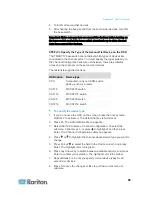
Page 93: ...hat connects these second tier devices is the base switch belonging to the FIRST TIER You can connect computers to any channel ports available in the system including channel ports on the base switch...

Page 94: ...establish a two tier system STEP A Programme an MCCAT switch as a second tier device STEP B Connect the second tier MCCAT switch to the base switch STEP C Specify the type of the second tier device on...

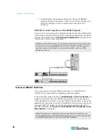
Page 95: ...You can mix different MCCAT models in the system Note This section describes the connection of two user MCCAT switches only To connect one user MCCAT switches see How to Connect MCCAT18 116 Switches...

Page 96: ...router CAT18 MCCAT18 switch CAT116 MCCAT116 switch CAT28 MCCAT28 switch CAT216 MCCAT216 switch To specify the device type 1 If you do not see the OSD on the screen press the hot key twice QUICKLY to a...

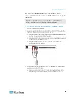
Page 97: ...ypes are used to connect computers to a second tier switch video or OSD issues may occur One User MCCAT Switches You can connect one user MCCAT switches to a TMCAT1728 or TMCAT17216 base switch for or...

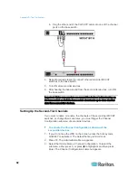
Page 98: ...to the MCCAT18 or MCCAT116 switch that has been programmed as a second tier device a Plug the MCIM s PS 2 keyboard connector into the PS 2 keyboard port on the second tier MCCAT switch b Plug the MCIM...

Page 99: ...nnel data from second tier devices Setting Up the Second Tier Channels If you want to name or rename the channels of the second tier MCCAT switches or change their scan rates you must trigger the Chan...

Page 100: ...el names that you specify after logging in to the base switch are saved in the database of the base switch not on each second tier device Therefore these channel names are unavailable when you access...

Page 101: ...r tasks with the second tier computers you can return to the Selection Menu of the TMCAT17 base switch for dealing with the computers connected to the base switch or accessing another second tier devi...

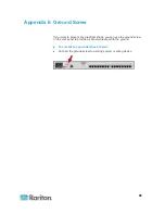
Page 102: ...ectrical shock you can use the ground screw on the rear panel to provide a safe electrical path to the ground To prevent any potential shock hazard Connect the ground screw to a wiring system or wirin...

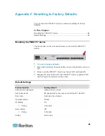
Page 103: ...nted tool such as a pen 2 Power cycle the TMCAT17 device by turing it OFF and back ON 3 Release the reset button after the TMCAT17 device is powered ON and the Login box appears on the screen Default...

Page 104: ...Appendix F Resetting to Factory Defaults 97 Field or function Factory default Login Blank Off Timing 5 minutes Logoff Timeout On Timing 5 minutes...

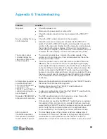
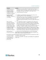
Page 105: ...e unstable If this is the case you will need to provide a proper ID pattern to the display card Call Raritan Technical Support see the last page for help if necessary All computers powered up without...

Page 106: ...when other computers are selected Try to identify if the problem is originating from the computer by reconnecting the computer to a different channel with a different cable Then turn on the computer I...

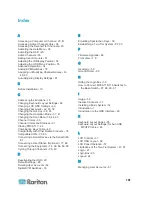
Page 107: ...n Keys Table 40 Compatibility with Other Raritan Products 78 Compatible CIMs 79 80 Connecting a Serial Device via the Serial CIM 81 Connecting a User Station Optional 17 66 Connecting the Equipment 14...

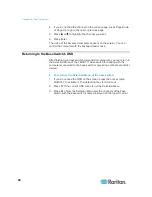
Page 108: ...CD Display 74 Resolutions for the External Monitor 74 Returning to the Base Switch s OSD 94 S Selection Menu 24 28 Setting Up the Channel ID Display Function 53 Setting Up the Green Mode 48 Setting Up...

Page 109: ...Index 103 W What are Active and Inactive Channels 5 30 36...

Page 110: ...India Monday Friday 9 a m 6 p m local time Phone 91 124 410 7881 Japan Monday Friday 9 30 a m 5 30 p m local time Phone 81 3 3523 5991 Email support japan raritan com Europe Europe Monday Friday 8 30...

Reviews: