background image


ALTERNA™ VF 

Contemporary Gas Heater 


This appliance may be installed in an aftermarket,  

permanently located, manufactured (mobile) home, 

where not prohibited by local codes.


This appliance is only for use with type of gas  

indicated on the rating plate.  This appliance is not  

convertible for use with other gases.  Field conversion 

is not permitted. Gas type conversion may only be  

accomplished at the factory.  Please contact Rasmussen 

for details.  

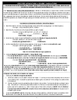
ATTENTION! READ INSTRUCTIONS CAREFULLY BEFORE ASSEMBLY OR USE


WARNING 

This appliance is for installation only in a solid-fuel burning masonry or UL 127 factory-built fireplace or in a listed   

ventless firebox enclosure.  It has been design certified for these installations.  Exception: DO NOT install this  

appliance in a factory-built fireplace that includes instructions stating it has not been tested or should not be used 

with unvented gas logs. 

FORM  286-L-05-5 

REV. 

5/19/2008 11:45 

Owner’s Manual 


ALTERNA VF Contemporary Gas Heaters are certified to the following standards:  

• 

UNVENTED ROOM HEATER ANSI - Z21.11.2-2007  

• 

VENTED DECORATIVE APPLIANCE - ANSI Z21.60b-2004 


General Assembly, Installation, and Operation Instructions  

® 

This is an unvented gas-fired heater.  It uses air 

(oxygen) from the room in which it is installed.   

Provisions for adequate combustion and ventilating 

air must be provided.  Refer to page 4. 

12028 E. PHILADELPHIA ST.   

WHITTIER, CA   90601   U.S.A.  

www.rasmussen.biz


THE GAS LOG COMPANY 

— Do not store or use gasoline or other flammable 

vapors and liquids in the vicinity of this or any other 

appliance. 


— WHAT TO DO IF YOU SMELL GAS


• 

Do not try to light any appliance. 


• 

Do not touch any electrical switch; do not use 

any phone in your building. 


• 

Immediately call your gas supplier from a 

neighbor’s phone. Follow the gas supplier’s  

instructions. 


• 

If you cannot reach your gas supplier, call the fire 

department.


— Installation and service must be performed by a  

qualified installer, service agency or the gas  

supplier.


WARNING: If the information in this manual is not  

followed exactly, a fire or explosion may result caus-

ing property damage, personal injury or loss of life. 

INSTALLER: Leave this manual with the appliance. 

CONSUMER: Retain this manual for future reference. 

Models

: AFB (20, 24, 30) - (ME, SE, RE) - (N, P)            AFG (20, 24, 30) - (ME, SE, RE) - (N, P) 


 AFS (20, 24, 30) - (ME, SE, RE) - (N, P) 

Installation must conform with local codes or, in the  
absence of local codes, with the National Fuel Gas Code, 
ANSI Z223.1/NFPA 54. 

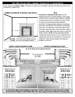
The Minimum Fireplace Size (in inches) in which this ALTERNA set is to be installed must be as follows:


Set Size 

Model Number 

BTU/hour  Front Width  Rear Width 

Depth 

Height 

20 

AFB20 - (ME,SE,RE) - (N,P) 

30,000 

26 

20 

11 

16 

24 

AFB24 - (ME,SE,RE) - (N,P) 

40,000 

30 

24 

11 

16 

30 

AFB30 - (ME,SE,RE) - (N,P) 

40,000 

36 

30 

11 

16 

IMPORTANT: 


An unvented room heater having an input rating of more than 10,000 Btu per hour shall not be installed  

in a bedroom or bathroom.  Do not install this appliance in a bedroom or bathroom. 

Summary of Contents for AFB20-ME-N

Page 1: ...E PHILADELPHIA ST WHITTIER CA 90601 U S A www rasmussen biz THE GAS LOG COMPANY Do not store or use gasoline or other flammable vapors and liquids in the vicinity of this or any other appliance WHAT TO DO IF YOU SMELL GAS Do not try to light any appliance Do not touch any electrical switch do not use any phone in your building Immediately call your gas supplier from a neighbor s phone Follow the g...

Page 2: ... and repair should be done by a qualified service person The appliance should be inspected before use and at least annually by a professional service person More frequent cleaning may be required due to excessive lint from carpeting bedding material etc It is imperative that control compartments burners and circulating air passageways of the appliance be kept clean WARNING Any change to this heate...

Page 3: ... 022AR 30 023 10A Pilot Location 10B Natural Gas Pilot Assembly ODS OP N 10C Propane Pilot Assembly ODS OP LP 11 3 8 Gas Output Tubing 12 Orifice Holder 12A Orifice Spud O1 varies with size gas 13 Piezo Push Button Igniter 13A Piezo Wire 14 Base support 15 3 8 Gas Input Tubing 16 Flex Connector SSCB 18 17 3 8 x 1 2 FIP EL A1 18 Damper Stop Clamp DC1 19 Black Volcanic Ash VA5 available separately 2...

Page 4: ...crease the Actual Btu Hr used by the same amount You may also choose to operate your ALTERNA as a Vented Appliance instead See notes and warnings regarding vented installation on Page 7 Adequate Combustion And Ventilation Air Options Increasing the Maximum Supportable Btu Hr 1 Add to the number of rooms which comprise the Space To do this you must either completely remove the door to an adjoining ...

Page 5: ...g joints between wall panels at penetrations for plumbing electrical and gas lines and at other openings VENT FREE APPLICATIONS COMBUSTION AIR CALCULATIONS COMBUSTION AIR CALCULATIONS WORKSHEET 1 Room Width Length Height W x L x H Vol ft 1a 1a 1b 1b 1c 1c 1d 1d 2 Total Volume ft The Sum of Volume of all rooms add lines 1a thru 1d 2 3 Max Supportable Btu Hr Total Volume ft 50 x 1000 divide line 2 b...

Page 6: ...n or warping due to heat However each and every decorative gas appliance installation ALTERNA included presents a different and completely unique set of circumstances involving many variables beyond the control of the manufacturer These include paint or finish composition previous exposure to heat methods and quality of construction air flow patterns glass doors fans or blowers etc Because of thes...

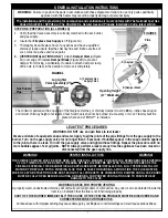
Page 7: ...he CSA B149 1 Natural Gas and Propane Installation Code latest edition STEP ONE PREPARATION ALL MODELS 1 Verify that the Valve Assembly is correctly matched to the set burner and gas supply 2 Insure that Fireplace Gas Supply is off Figure 1A 3 Thoroughly clean fireplace floor of any ashes and have a qualified chimney cleaner insure that the chimney flue and firebox are free of soot creosote ashes ...

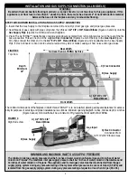
Page 8: ...eads of gas supply with pipe compound then thread 1 2 FIP x 3 8 Flared Elbow Figures 3 and 4A onto the Gas Supply Pipe Figures 3 and 4B and wrench tighten 3 Place The ALTERNA inside firebox or approved enclosure centered from left to right and as far to the rear of the fire box as possible Thread one end of the supplied Flex Connector Figures 3 and 4C below to the Gas Input Figure 4D then connect ...

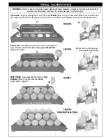
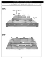
Page 9: ...irst row with flat side resting against Flame Rod Figure 6A and B FIGURE 6 FIGURE 5 A FIGURE 7 First two rows of full fireballs in position B Second row with flat side resting against Flame Rod STEP THREE Now place the third row of 4 Half FireBalls FB 4H into the crescent shaped locator holes Figure 7 FIGURE 8 Completed Fireball Setup A WARNING Failure to position the parts in accordance with thes...

Page 10: ...ith fewer FireBalls See previous page for placement details Bottom Row FB 4 x 4 Middle Row FB 4 x 4 Top Row FB 4H x 3 Bottom Row FB 4 x 5 FIGURE 9 AFB20 FIGURE 10 AFB24 WARNING Failure to position the parts in accordance with these diagrams or failure to use only parts specifically approved with this heater may result in property damage or personal injury ...

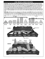
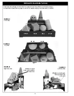
Page 11: ...Figures 12 and 15 A Cylinder CY 63 will fit into the 2nd hole from the right at a slight angle resting against the Flame Rod Figures 14B and 15B Last place the CO 55 Cone into the first locator hole on the right leaning slightly forward into locator hole Figure 14D STEP TWO Begin the second row by placing the second flat topped Cone CO 63 directly over the top left locator hole Figure 13B Next pla...

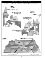
Page 12: ... against Flame Rod FIGURE 14 Right Side View B CY 63 at a slight angle resting against Flame Rod C PY3 44 leaning slightly forward C FB 4H with flat side facing rear wall See Figures 13 14 and 15 below for a further explanation of the ALTERNA 24 FireShapes placement PY4 44 CO 63 CO 55 PY3 44 CY 63 PY4 44 FB 4 CO 63 CU 44 CY 63 CO 55 PY3 44 FB 4H CY 63 CO 63 D CO 55 Leaning forward into locator hol...

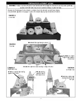
Page 13: ... facing rear wall PY4 44 FB 4 CO 63 CU 44 CY 63 PY3 44 FB 4H CO 63 PY4 44 FB 4 CO 63 CU 44 CY 63 PY3 44 FB 4H CO 63 FIGURE 16 Front View FIGURE 18 Right Side View Placement of FireShapes for the AFG24 is similar to that of the AFG30 but with fewer objects Consult AFG30 placement on pages 11 and 12 for detailed step by step instructions if needed CY 63 PY3 44 PY4 44 CO 63 WARNING Failure to positio...

Page 14: ...ent of FireShapes for the AFG20 is similar to that of the AFG30 but with fewer shapes Consult AFG30 placement on pages 11 and 12 for detailed step by step instructions if needed FIGURE 22 Right Side View FIGURE 23 Left Side View PY4 44 at a slight angle leaning forward and to the right PY4 44 CY 63 at a slight angle resting against Flame Rod CY 63 ...

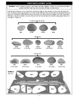
Page 15: ...ne and its corresponding locator hole The lower portion approximately 1 4 to 1 2 of each FireStone on the top row will fit into the locator holes see Figure 22 FireStones on the bottom row are to be placed over each locator hole Figures 22 and 23 Place each FireStone on the 2nd or middle row on top of those on the first row with back side of each resting against Flame Rod see page 17 Figure 25 WAR...

Page 16: ...T19 ST4 ST21 ST11 ST1 ST3 ST17 ST19 ST2 FIRESTONES PLACEMENT AFS30 CONTINUED ST4 leans slightly against ST21 WARNING Failure to position the parts in accordance with these diagrams or failure to use only parts specifically approved with this heater may result in property damage or personal injury ...

Page 17: ...T15 ST20 and ST10 shown above resting against Flame Rod ST1 ST3 ST17 ST19 ST2 ST19 ST4 ST21 ST11 ST15 ST16 ST10 ST20 ST18 The AFS30 should look like the illustration above when completed Flame Rod ST19 under ST20 not visible from this angle WARNING Failure to position the parts in accordance with these diagrams or failure to use only parts specifically approved with this heater may result in prope...

Page 18: ...IRESTONES PLACEMENT AFS20 AND 24 Placement of FireStones for the AFS20 and AFS24 is similar to that of the AFS30 with the exception of a few removed stones on the right side of the appliance The AFS24 includes all eight FireStones on the right with the addition of the three FireStones on the left AFS20 and AFS 24 FIGURE 29 AFS20 FIGURE 30 AFS24 Top View Top View Front View Front View WARNING Failu...

Page 19: ...re in the receiver If tis happens move the receiver into a cooler area and or use the RH3 remote house REMOTE RECEIVER PLACEMENT SE AND RE MODELS FIGURE 31 C Black Volcanic Ash used as Floor dressing The Remote Receiver RE and SE models Figure 31 can be adversely affected by heat and must be placed as far forward and to the side of your ALTERNA as possible Figure 31A Our optional Ceramic Remote Ho...

Page 20: ...nt the burner begins to shutdown re adjust for a longer pilot flame 4 Slowly turn Valve Knob to ON to light burner If burner fails to light or if pilot goes out repeat steps 1 through 4 5 Adjust the burner flame height by turning the EASY Safety Valve Knob clockwise to lower and counter clockwise to raise up to full on Figure 32 6 For complete shutdown push EASY Safety Valve in and turn to OFF FIG...

Page 21: ... ON HI button one beep at a time will raise the burner flame To verify the burner is com FIGURE 38 FIGURE 36 Slide Switch in REMOTE Position Wireless On Off Remote with Thermostat THR 2R Wireless Wall Thermostat TS 2R Accessory Controls Wireless Wall Timer 30 60 120 Minutes WT 2R Wireless On Off Remote SR 2R Wireless Wall Switch WS 2R B Pilot Adjustment Screw A EASY Safety Valve Knob C Knob Positi...

Page 22: ...ere flame comes out of the burner should be periodically cleaned of debris Use compressed air and or a soft bristle brush to clean burner ports and air shutter area Air shutters should not be altered from factory settings WARNING Failure to keep the burner primary air opening clean may result in sooting or property damage Keep air intake holes of ODS Pilot see Page 20 Figure 34 clear of lint Over ...

Page 23: ...falls between the minimum and maximum pressures allowed with this gas set refer to the tables pages 5 and 6 Blocked ports low flame only Free the main burner orifice and burner bar ports of any burrs paint or other blockage No Spark at Pilot when Depressing Piezo Igniter Most likely cause Wire connecting push button with pilot has become disconnected Fix Reconnect wire Receiver Beeps SE and RE Mod...

Page 24: ...of incidental or consequential damages so the above limitation or exclusion may not apply to you 3 The maximum liability of RASMUSSEN in connection with this limited warranty shall not in any case exceed the contract price paid for the product claimed to be defective or unsuitable 4 This warranty does not extend to any product manufactured by RASMUSSEN which has been subjected to misuse neglect ac...

Reviews: