ALL APPLICATIONS (VENTED and VENT FREE OPERATION)
CBR-T (Thermostatic Control) Pilot Lighting, Operation, And Shutting Down:
Pilot Lighting:
1. Turn KNOB "A" (Main Gas Control) clockwise to
"O F F " position. S e e F i g u r e 1 1 .
2. Turn KNOB "B"
(Rear Gas Burner
Thermostat) clockwise to lowest setting "1 ".
3. Wait five (5) minutes before lighting.
4. Turn KNOB "A"(Main Gas Control) slightly
counter-clockwise towards the "IGN" position until
reaching stop. Press down and hold until air is bled and
gas flows to the pilot.
5. Continue pressing down while turning KNOB "A"
(Main Gas Control)
further counter clockwise to
activate piezo. Continue to hold down for ten (10)
seconds after pilot burner has been lit. If pilot does not
light, repeat steps 4 and 5.
6. Adjust pilot to ensure adequate coverage of
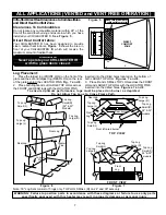
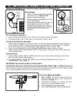
Thermocouple. See Figure 10
Rear Gas Burner Operation:
7. Once pilot has been lit, release KNOB "A" (Main
Gas Control) and turn further counter clockwise to the
"O N " position.S e e F i g u r e 1 1 .
8. Turn KNOB "B"(Main Gas Control) counter
clockwise to the desired demand setting. The Rear Gas
Burner will then modulate (between "Off" and "High") in
response to this selected setting.
9. To turn only the Rear Gas Burner off, turn KNOB
"B" (Main Gas Control) clockwise to the setting "1".
NOTE: Turning KNOB "A" (Main Gas Control) to
"OFF" simultaneously stops gas flow to both the Front
Infra-Red burner and the Rear Gas Burner.
.
.
.
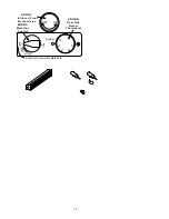
Pilot Set Screw under plate here.
OFF ON
KNOB C
Infra-red Front
Burner Valve
KNOB A
Main Gas Control
KNOB B
Rear Gas
Burner
Thermostat
Figure 11
Infra-Red (front) Heater Operation:
10. To light the front INFRA-RED Burner, Turn
KNOB "A" (Main Gas Control) to the “O N ” position
then turn KNOB "C" (Infra-Red Front Burner
Valve) counter clockwise to "ON". If the Infra-Red
burner fails to light repeat steps 1 through 5 above. The
Infra-Red burner will not operate unless KNOB "A"
(Main Gas Control) is turned to “O N ”. See Figure 11.
11. To turn only the Infra-Red Heater off, turn KNOB "C"
(Infra-Red Front Burner Valve) clockwise to
"OFF". NOTE: Turning KNOB "A" (Main Gas
Control) to "OFF" stops gas flow to both the Rear Gas
Burner and the Front Infra-Red burner simultaneously.
Shutting Down:
11. Turning KNOB "A" (Main Gas Control) to "OFF" allows the pilot to remain lit while shutting down both the
Rear Gas Burner and the Front Infra-Red Heater. S e e F i g u r e 1 1 .
12. For complete shutdown, including pilot, slightly push control KNOB "A" (Main Gas Control) knob in and turn
Clockwise to "OFF”.
Sequence Of Operation:
•
Turning KNOB "A" (Main Gas Control) to "ON" sends gas to the Rear Gas Burner, Front Burner
Lighter Tube, and up to KNOB "C".
KNOB "C"
(Infra-Red Front Burner Valve) in the "ON" position
allows gas to flow to the front INFRA-RED Burner which is lit by the the Front Burner Lighter Tube flame.
NOTE: KNOB "A" (Main Gas Control) must be "ON" to operate the Front Infra-Red Burner. See
Figure 11.
Thermostat Operation:
1. Basic Operation: The thermostat setting, KNOB "B" (Main Gas Control), directly effects the height of
the Rear Gas Burner flame. (Note: The thermostat setting has no effect on the Front Infra-Red
Burner.) The Rear Gas Burner flame will modulate from "Off" to "High" based upon the difference between
the selected setting on Knob "B" and the room air temperature as sensed by the THERMOSTAT SENSOR
BULB. If the room air temperature is less than the selected setting, the Rear Gas Burner flame will be in the
"High" range. Conversely, if the room air temperature is greater or equal to the selected setting, the Rear Gas
Burner flame will be smaller or completely extinguished. S e e F i g u r e 1 1 .
2. Adjusting Temperature: Turn Knob "B" (Main Gas Control) toward higher numbers (max 7 ) to increase
temperature, toward the lower numbers (1 ) to decrease temperature. S e e F i g u r e 1 1 .
3.
Burner Cycling: With Knob A in the "ON" position, the Rear Gas Burner flame will modulate up and down
to meet the selected setting on Knob "B" (Main Gas Control). The Front Infra-Red Heater does not
modulate. S e e F i g u r e 1 1 .
4.
Ignition Interlock: The Ignition Interlock device prevents the re-establishment of gas flow following a loss of
pilot flame until the thermocouple has cooled sufficiently. (Approximately five minutes).
9

